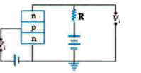
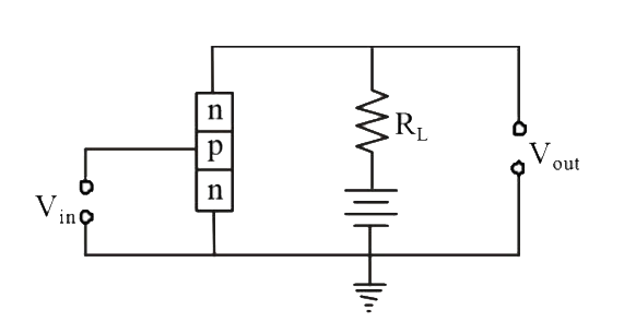
An n-p-n tansistor circuit is show below

The arrangement represent a
A
a common - collector amplifier circuit
B
a common - emitter amplifier circuit
C
a common - base amplifier circuit
D
a switch circuit
Video Solution
Text Solution
Here the emitter is forward biased and also it is So, it is a common emitter smplifier ciruit
|
Topper's Solved these Questions
- SEMICONDUCTOR ELECTRONICS METERIALS DEVICES AND SIMPLE CIRCUITS BOOK - MODERN PUBLICATIONCHAPTER - SEMICONDUCTOR ELECTRONICS METERIALS DEVICES AND SIMPLE CIRCUITS EXERCISE - COMPETION FILE (JEE(MAIN) & OTHER STATE BOARDS FOR ENGINEERING ENTRANCE )
31 Videos
- SEMICONDUCTOR ELECTRONICS METERIALS DEVICES AND SIMPLE CIRCUITS BOOK - MODERN PUBLICATIONCHAPTER - SEMICONDUCTOR ELECTRONICS METERIALS DEVICES AND SIMPLE CIRCUITS EXERCISE - COMPETION FILE( MULTIPLE CHOICE QUESTIONS )
17 Videos
- SEMICONDUCTOR ELECTRONICS METERIALS DEVICES AND SIMPLE CIRCUITS BOOK - MODERN PUBLICATIONCHAPTER - SEMICONDUCTOR ELECTRONICS METERIALS DEVICES AND SIMPLE CIRCUITS EXERCISE - REVISION EXERCISES (NUMERICAL PROBLEMS )
15 Videos
- RAY OPTICS AND OPTICAL INSTRUMENTSBOOK - MODERN PUBLICATIONCHAPTER - RAY OPTICS AND OPTICAL INSTRUMENTSEXERCISE - CHAPTER PRACTICE TEST
14 Videos
- WAVE OPTICALBOOK - MODERN PUBLICATIONCHAPTER - WAVE OPTICALEXERCISE - CHAPTER PRACTICE TEST
7 Videos
Similar Questions
Knowledge Check
In n−p−n transistor the arrow head on emitter represents that the convantional current flows from
Abase to emitterBemitter to baseCemitter to collectorDbase to collectorActive state of n-p-n transistor, in circuit is achieved by
ALow input voltageBHigh input voltageCBoth (low input voltage) and (high input voltage)DNeither (low input voltage) nor (high input voltage)Active state of n-p-n transistor, in circuit is achieved by
Alow input voltageBhigh input voltageCboth a and bDNeither a nor b
In n-p-n transistor, what are the current carriers inside and outside the transistor circuit?
View SolutionIn the diagram give n below shaded part represents :-

View SolutionThe diagram of a logic circuit is given below. The output F of the circuit is represented by

View SolutionIn an n-p-n transistor circuit, the collector current ia 10 mA. If 90% of the electrons emitted reach the collector.
View SolutionIn an n-p-n transistor circuit, the collector current is 20 mA. If 90 % of electron emitted reach the collector :-
View Solution


