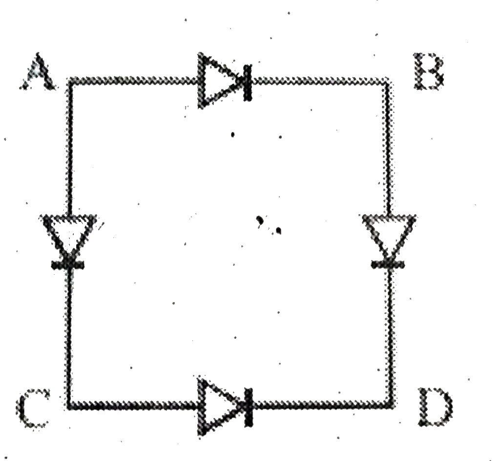
Four diodes are connected in the adjoining in order for the circuit toact as a full wave DC output are connected and obtained respectively across

BA and CD
BD and AC
BC and AD
AD and BD
Step by step video & image solution for Four diodes are connected in the adjoining in order for the circuit toact as a full wave DC output are connected and obtained respectively across by Physics experts to help you in doubts & scoring excellent marks in Class 12 exams.
Updated on:21/07/2023Topper's Solved these Questions
- SEMICONDUCTOR ELECTRONICS METERIALS DEVICES AND SIMPLE CIRCUITS BOOK - MODERN PUBLICATIONCHAPTER - SEMICONDUCTOR ELECTRONICS METERIALS DEVICES AND SIMPLE CIRCUITS EXERCISE - COMPETION FILE (JEE(MAIN) & OTHER STATE BOARDS FOR ENGINEERING ENTRANCE )
31 Videos
- SEMICONDUCTOR ELECTRONICS METERIALS DEVICES AND SIMPLE CIRCUITS BOOK - MODERN PUBLICATIONCHAPTER - SEMICONDUCTOR ELECTRONICS METERIALS DEVICES AND SIMPLE CIRCUITS EXERCISE - COMPETION FILE( MULTIPLE CHOICE QUESTIONS )
17 Videos
- SEMICONDUCTOR ELECTRONICS METERIALS DEVICES AND SIMPLE CIRCUITS BOOK - MODERN PUBLICATIONCHAPTER - SEMICONDUCTOR ELECTRONICS METERIALS DEVICES AND SIMPLE CIRCUITS EXERCISE - REVISION EXERCISES (NUMERICAL PROBLEMS )
15 Videos
- RAY OPTICS AND OPTICAL INSTRUMENTSBOOK - MODERN PUBLICATIONCHAPTER - RAY OPTICS AND OPTICAL INSTRUMENTSEXERCISE - CHAPTER PRACTICE TEST
14 Videos
- WAVE OPTICALBOOK - MODERN PUBLICATIONCHAPTER - WAVE OPTICALEXERCISE - CHAPTER PRACTICE TEST
7 Videos
Similar Questions
Knowledge Check
4 ideal diodes are connected as shown in the circuit the current through 50Ω is.
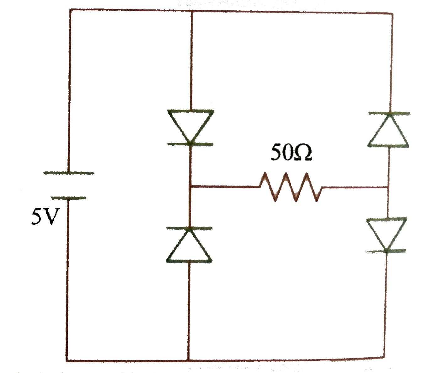 .A0.1AB0.5AC0.6AD1A
Two ideal diodes are connected to a battery as shown in the circuit. The current supplied by the battery is
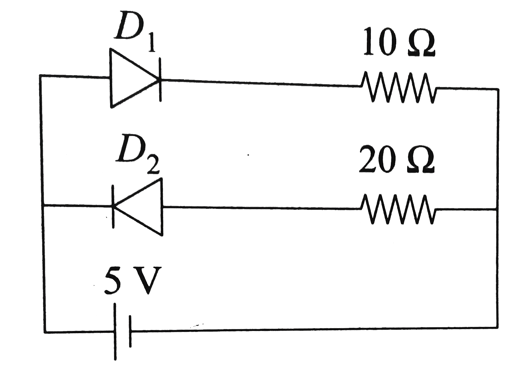 A0.75AB0C0.25AD0.5A
Two ideal diodes are connected to a battery as shown in the circuit. The current supplied by the battery is
 A0.75 ABzeroC0.25 AD0.5 A
Three resistors of 5Ω,10Ωand15Ω are connected in series and the combination is connected to battery of 30 V. Ammeter and Voltmeter are connected in the circuit. Draw a circuit diagram to connect all the devices in proper correct order. What is the corrent flowing and potential difference across 10Ω resistance?
View Solution" Four silicon diodes are connected as shows in fig Assuming the diodes to be ideal The current through the resister is "
View SolutionTwo ideal diodes are connected to a battery as shown in the circuit. The current supplied by the battery is

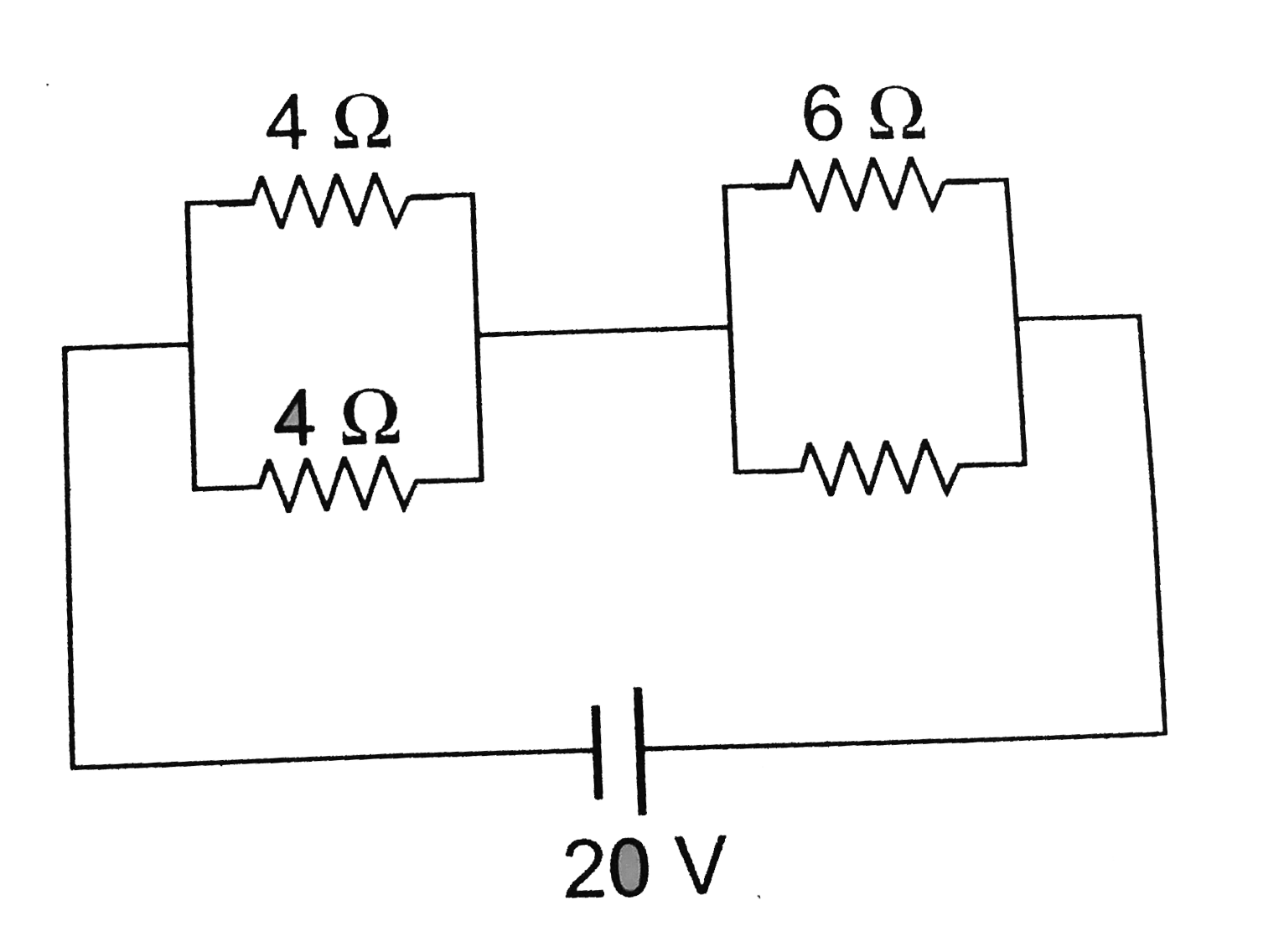
View SolutionFour resistances are connected in a circuit in the given figure. The electric cirrent flowing through 4ohm and 6ohm resistance is respectively
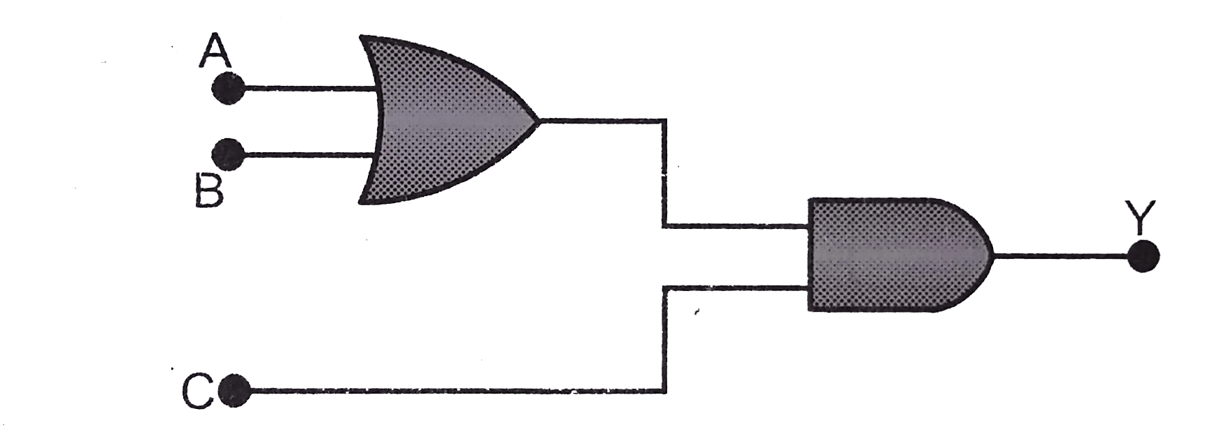
View SolutionIn order to obtain an output Y=1 form the circuit of fig. the inputs must be
View Solution

