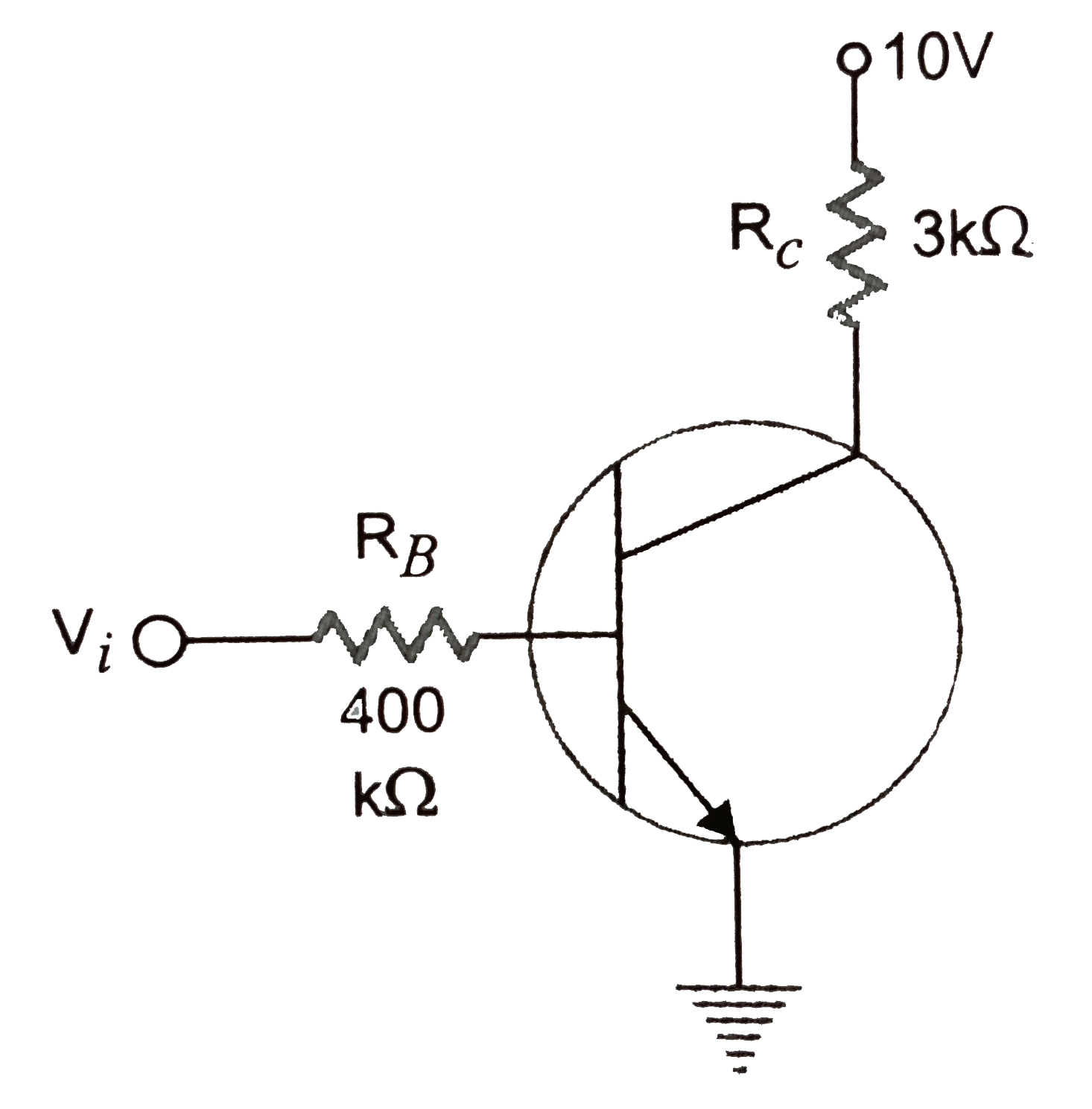
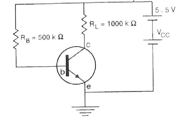
In the circuit given below input voltage at the base resistance is 10 V also VBE and VCE are zero for the circuit if
1000IB−Ic×β15V0RB=4x×10y
calculate the value of xy


Applying kirchhoffs loop rule in the collecter emitter circuit
⇒Ic=Vcc−VceRl=10−01kΣ=10mA
=25−10×103×400×400×103150
Comparing with 4x×10y we get
x=2 and y=3
xy=2×3=6
Topper's Solved these Questions
- BOOK - MODERN PUBLICATIONCHAPTER - SEMICONDUCTOR ELECTRONICS METERIALS DEVICES AND SIMPLE CIRCUITS EXERCISE - COMPETION FILE (NCERT EXEMPLAR PROBLEMS :MULTIPLE CHOICE QUESTION TYPE -I)8videos
SEMICONDUCTOR ELECTRONICS METERIALS DEVICES AND SIMPLE CIRCUITS
- BOOK - MODERN PUBLICATIONCHAPTER - SEMICONDUCTOR ELECTRONICS METERIALS DEVICES AND SIMPLE CIRCUITS EXERCISE - COMPETION FILE (NCERT EXEMPLAR PROBLEMS :MULTIPLE CHOICE QUESTION TYPE -II)8videos
SEMICONDUCTOR ELECTRONICS METERIALS DEVICES AND SIMPLE CIRCUITS
- BOOK - MODERN PUBLICATIONCHAPTER - SEMICONDUCTOR ELECTRONICS METERIALS DEVICES AND SIMPLE CIRCUITS EXERCISE - COMPETION FILE (MATRIX MATCH TYPE QUESTIONS)2videos
SEMICONDUCTOR ELECTRONICS METERIALS DEVICES AND SIMPLE CIRCUITS
- BOOK - MODERN PUBLICATIONCHAPTER - RAY OPTICS AND OPTICAL INSTRUMENTSEXERCISE - CHAPTER PRACTICE TEST14videos
RAY OPTICS AND OPTICAL INSTRUMENTS
- BOOK - MODERN PUBLICATIONCHAPTER - WAVE OPTICALEXERCISE - CHAPTER PRACTICE TEST7videos
WAVE OPTICAL
Similar Questions
In the circuit shown in Fig. when the input voltage of the base resistance is 10V,Vbe is zero and Vce is also zero. Find the values of I,I and β.
 View Solution
In the circuit shown in Fig. when the input voltage of the base resistance is 10V,Vbe is zero and Vce is also zero. Find the values of I,I and β.
 View Solution
Knowledge Check
- Question 1 - Select One
In the circuit shown in figure, when the input voltage of the base resistance is 10 V, Vbe is zero and Vce is also zero. Then
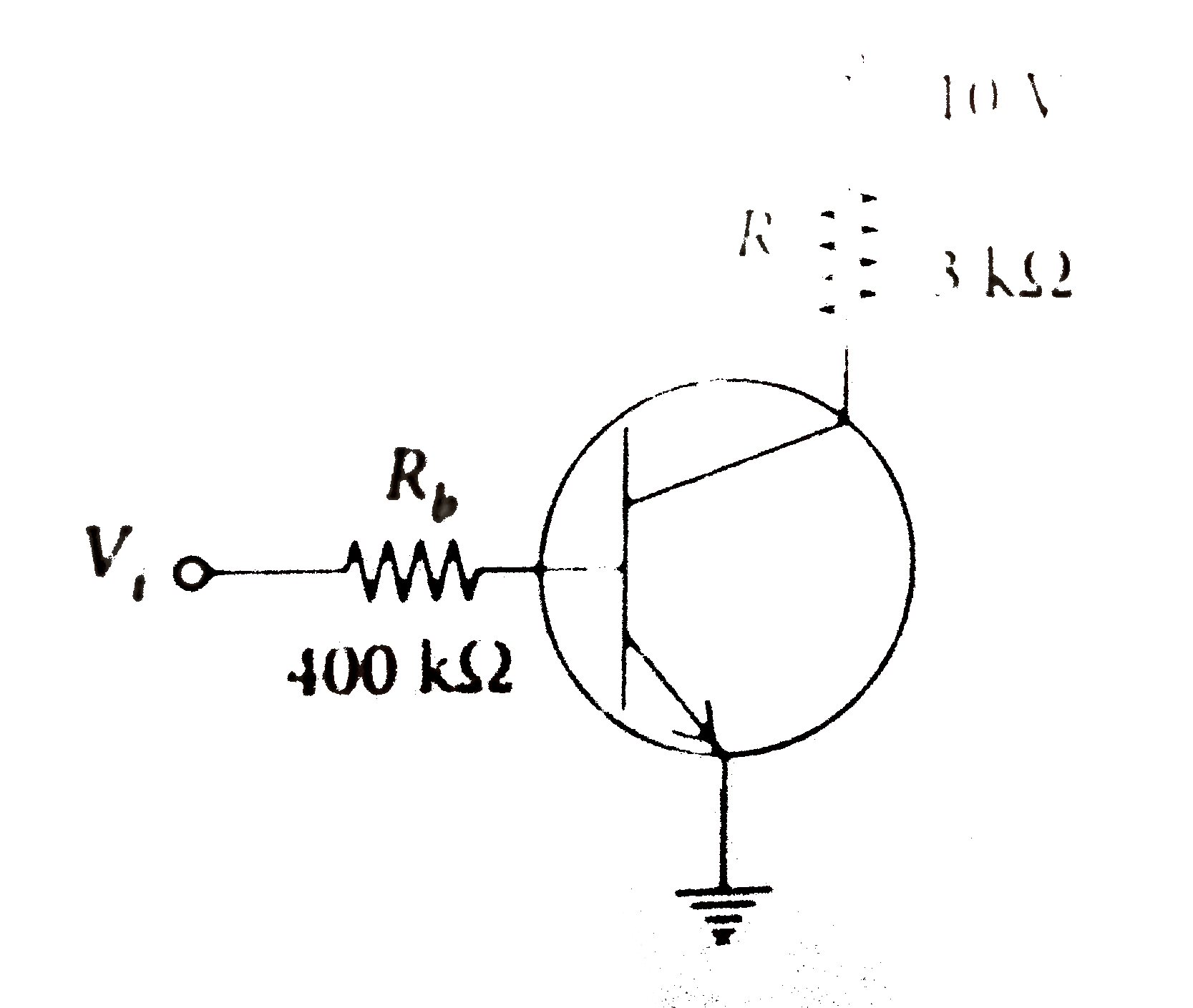 Aβ=110BIb=25μACIc=3.33mADboth (A) and (C )
 - Question 2 - Select One
In the circuit shown in figure, when the input voltage of the base resistance is 10 V, Vbe is zero and Vce is also zero. Then
 Aβ=110BIb=25μACIc=3.33mADboth (A) and (C )
 - Question 3 - Select One
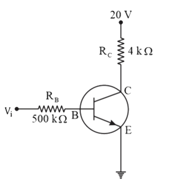
In the circuit shown in the figure, the input voltage Vi is 20V, VBE=0 and VCE=0. The values of IB, IC and β are given by
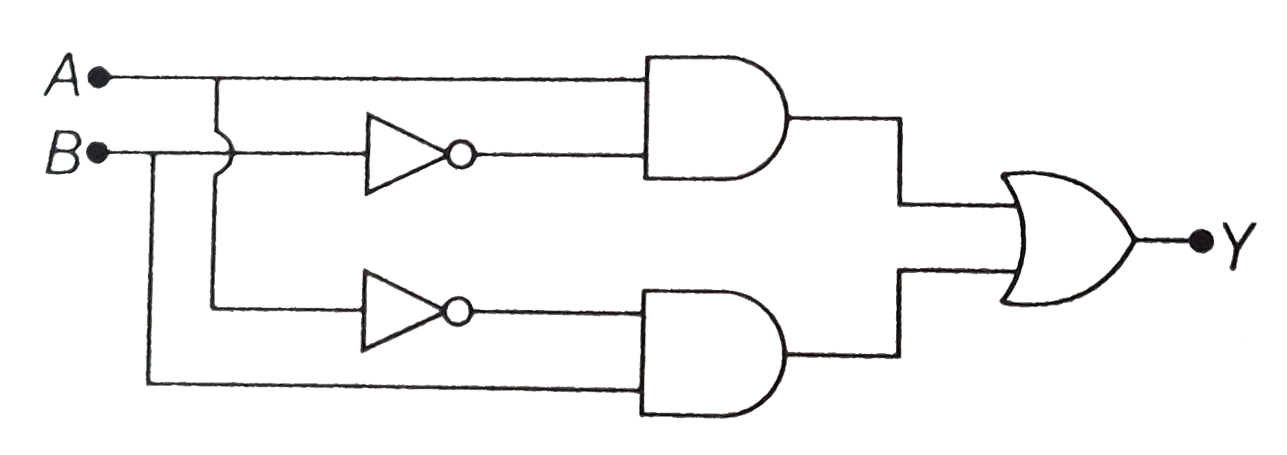 A¯¯¯¯¯¯¯¯A.B+A.BBA.¯¯¯B+¯¯¯A.BC¯¯¯¯¯¯¯¯A.BD¯¯¯¯¯¯¯¯¯¯¯A+B
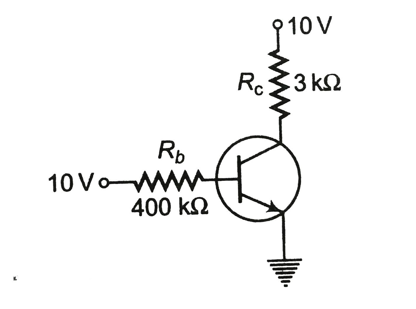
In the circuit shown in figure when the input voltage of the base resistance is 10 V . Find the values of Ib,Icandβ .
 View Solution
In the circuit shown in figure when the input voltage of the base resistance is 10 V . Find the values of Ib,Icandβ .
 View Solution
In the accompanying circuit Fig. 5.10, if it is assumed that when that input voltage at the base resistance is 5 V, VBE is zero and VCE is also zero, what are IB,ICandβ ? When the input is zero, IB is zero. What will be the output waveform if the input waveform is as shown in the figure ? What is the practial use of this current ?
 View Solution
In the circuit shown in Fig.
if we assume that when the input voltage at the base resistance is 5V,VBE is zero and VCE is also zero. What is I,I and beta?
When the input is zero, then I is zero. What would be the output wave form if the input wave form is as shown in Fig.View SolutionIn the circuit shows in the figure, the input voltage
Vi is 20 V, VBE=0 and VCE=0. The values of lB,lC and β are given by
 View Solution

