The magnetic flux through each of give faces of a neutral playing dice is given ϕB=±NWb,whereN(=1to5) is the number of spots on the face. The flux is positive (out -ward) for N even and negative (inward) for N odd What is the flux through sixth face of the die ?
+3 Wb
Topper's Solved these Questions
- ELECTROMAGNETIC INDUCTIONBook:RESNICK AND HALLIDAYChapter:ELECTROMAGNETIC INDUCTIONExercise:PRACTICE QUESTIONS (Single Correct Choice Type)
Explore 45 Videos
- ELECTROMAGNETIC INDUCTIONBook:RESNICK AND HALLIDAYChapter:ELECTROMAGNETIC INDUCTIONExercise:PRACTICE QUESTIONS (More than One Correct Choice Type)
Explore 13 Videos
- ELECTROMAGNETIC INDUCTIONBook:RESNICK AND HALLIDAYChapter:ELECTROMAGNETIC INDUCTIONExercise:CHECKPOINTS
Explore 9 Videos
- ELECTRIC POTENTIALBook:RESNICK AND HALLIDAYChapter:ELECTRIC POTENTIALExercise:(PRACTICE QUESTIONS) Integer Type
Explore 1 Video
- ELECTROMAGNETIC OSCILLATIONS AND ALTERNATING CURRENT Book:RESNICK AND HALLIDAYChapter:ELECTROMAGNETIC OSCILLATIONS AND ALTERNATING CURRENT Exercise:Practice Questions (Integer)
Explore 7 Videos
Similar Questions
the net electric flux through each face of a die (singular of dice) has a magnitude in units of 103N.m2/C that is exactly equal to the number of sport N on the face ( 1 through 6) the flux is inward for N odd out word for N even. What is the net charge inside the die ?
View SolutionThe magnetic flux through a loop is varying according to relation ϕ=6t2+7t+1 where ϕ is in milliweber and t is in second. What is the e.m.f. induced in the loop at t = 2 second ?
View Solution
Knowledge Check
The magnetic flux through each of give faces of a neutral playing dice is given ϕB=±NWb,whereN(=1to5) is the number of spots on the face. The flux is positive (out -ward) for N even and negative (inward) for N odd What is the flux thogh sixth face of the die ?
A3WbB4WbC−3WbD−4WbThe magnetic flux ϕ linked with a conducting coil depends on time as ϕ=4tn+6, where n is positive constant. The induced emf in the coil is e
AIf 0<n<1,e≠0 and |e| decreases with time.BIf n=1, e is constantCIf n>1,|e| increases with time.DIf n>1,|e| decreases with time.A capacitor can be used to produce a desired electric field. We consldered the parallel plate arrangement as a basic type of capacitor. Similarly, an inductor (symbol ) con be used to near the middle of a long solenoid ) as our basic type fo inductor.
if we establish a current i in the winding ( or turns ) of an inductro ( a solenoid ) the current produces a magnetic flux ϕB through the central region of the inductor. the inductance of the inductor is then
[L=NϕEi] ( inductance defined )
where N is the number of turns. the windings of the inductor are said to the linked by the shared flux, and the product NϕE is called the magnetic flux linkage . the inductance L is thus a measure of flux produced by the inductor per unit of current . Now, consider a special type of inductor whose radius of turn R as shown in the adjacent figure and total number of turns is N.
This special type of solenoid produces a magnetic field ∣∣→B∣∣=μlr2 uniformly along the axis of the solenoid as shown in figure. r is the distance from the axis of solenoid.

If it is given that total flux linkage through the inductor is KIL2 (where L is the inductance). then its inductance is given byAKBK2C1/KD1/K2
The magnetic flux through a coil varies with time t as follows:
ϕt=(8t3−6t2+t−5)Wb
What is the induced current through the coil at t = 4 s, given that the resistance of the coil is 10 Ω and the magnetic flux through the coil is perpendicular to its plane?
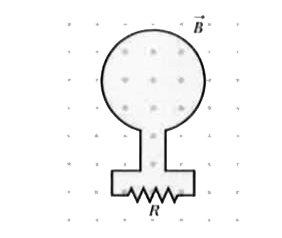
View SolutionIn Fig. 30-60, the magnetic flux through the loop increases according to the relation ϕB=3.0t2=7.0t, where ϕB is in milliwebers and tis in seconds. (a) What is the magnitude of the emf induced in the loop when t = 1.5 s? (b) Is the direction of the current through R to the right or left?

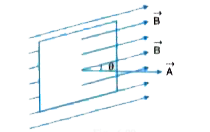
View SolutionMagnetic flux ϕB through a plane of area 'A' placed in a uniform magnetic field vceB is given as:
ϕB=vceB.vceA=BAcosθ

where θ is the angle between vceB and vceA. The above relatio can be extended to curved surfaces and non-uniform fields. In general, if the magnetic field has different magnitudes an directions at various parts of a surface, then the magnetic flux through the surface is given by
ϕB=∫→B.d→A
On the basis of the experimental observations, Faraday concluded that an emf is induced in a coil when magnetic flux through the coil changes with time. Faraday stated his conclusions in the form of a law called Faraday's law of electromagnetic induction. As per this law, the induced emf is given by
ɛ=−dϕBdt
The negative sign in the expression indicates the direction of induced emfe and hence the direction of current in a closed loop.
In the case of a closely would coil of N turns, change of flux associated with each turns is the same and so that total induced emf is given by ɛ=−NdϕBdt
From above relations it is clear that the magnetic flux can be changed by changing any one or more of the terms vceB,vceAandθ.
(a) Give SI unit of magnetic flux.
(b) How is it related to tesla ?
(c) Obtain dimensional formula of magnetic flux.
(d) A loop of area 4×10⁻³m2 is placed with its plane perpendicular to a uniform magnetic field of 0.02 T. If the loop is quickly removed from the magnetic field within a time of 2 ms, what is the magnitude of induced emf across the two ends of the loop ?
(e) If the resistance of the loop be 0.2Ω and a sensitive milliammeter be connected between the two ends of loop, what will be the reading of milliammeter?
View SolutionA capacitor can be used to produce a desired electric field. We consldered the parallel plate arrangement as a basic type of capacitor. Similarly, an inductor (symbol ) con be used to near the middle of a long solenoid ) as our basic type fo inductor.
if we establish a current i in the winding ( or turns ) of an inductro ( a solenoid ) the current produces a magnetic flux ϕB through the central region of the inductor. the inductance of the inductor is then
[L=NϕEi] ( inductance defined )
where N is the number of turns. the windings of the inductor are said to the linked by the shared flux, and the product NϕE is called the magnetic flux linkage . the inductance L is thus a measure of flux produced by the inductor per unit of current . Now, consider a special type of inductor whose radius of turn R as shown in the adjacent figure and total number of turns is N.
This special type of solenoid produces a magnetic field ∣∣→B∣∣=μlr2 uniformly along the axis of the solenoid as shown in figure. r is the distance from the axis of solenoid.

The value of total flux linkages when current l flows through this special type of inductor is given by
View SolutionA capacitor can be used to produce a desired electric field. We consldered the parallel plate arrangement as a basic type of capacitor. Similarly, an inductor (symbol ) con be used to near the middle of a long solenoid ) as our basic type fo inductor.
if we establish a current i in the winding ( or turns ) of an inductro ( a solenoid ) the current produces a magnetic flux ϕB through the central region of the inductor. the inductance of the inductor is then
[L=NϕEi] ( inductance defined )
where N is the number of turns. the windings of the inductor are said to the linked by the shared flux, and the product NϕE is called the magnetic flux linkage . the inductance L is thus a measure of flux produced by the inductor per unit of current . Now, consider a special type of inductor whose radius of turn R as shown in the adjacent figure and total number of turns is N.
This special type of solenoid produces a magnetic field ∣∣→B∣∣=μlr2 uniformly along the axis of the solenoid as shown in figure. r is the distance from the axis of solenoid.

If an external magneitc field →B perperdicular to the axis of the solenoid is applied, then total flux linkage will
View Solution