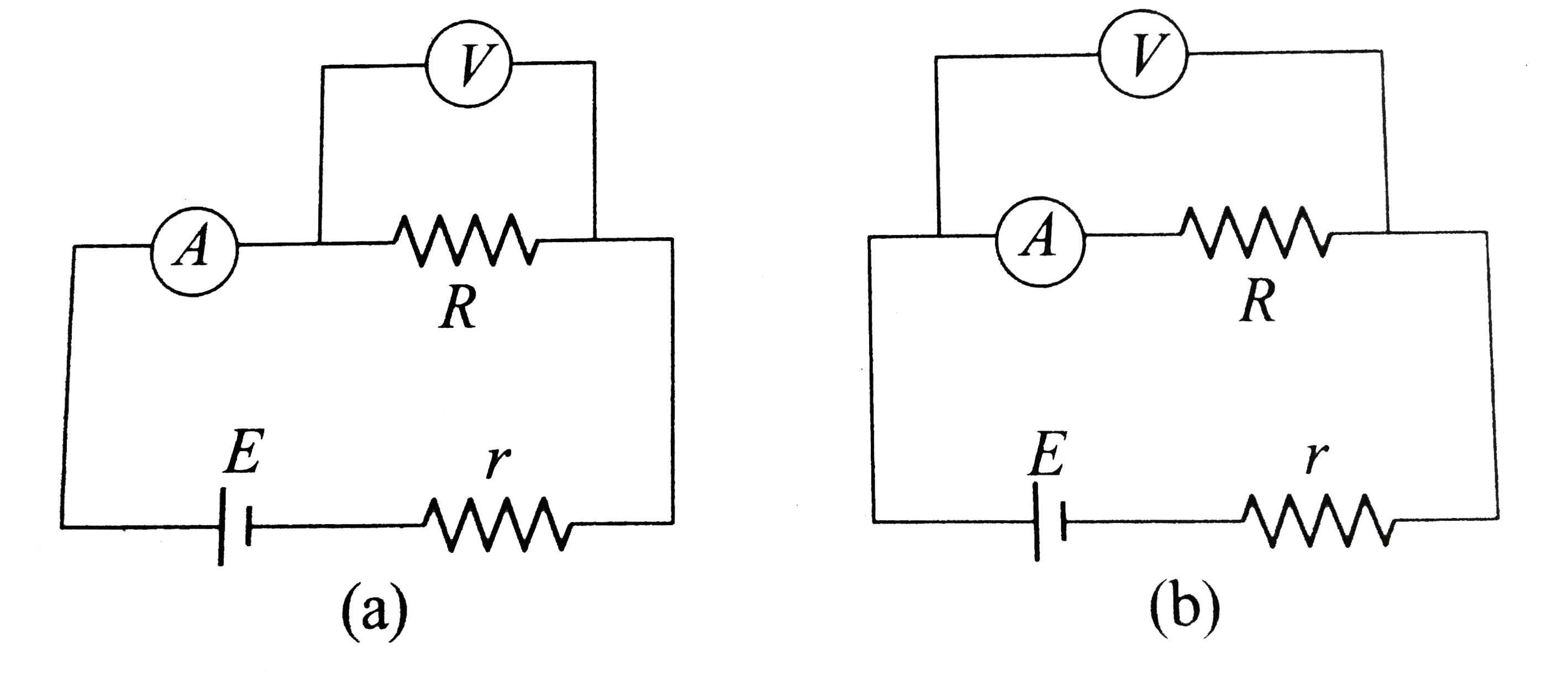
The actual value of resistance R, shown in the figure is 30Ω. This is measured in an experiment as shown using the standard formula R=VI, where V and I are the reading of the voltmeter and ammeter, respectively. If the measured value of R is 5% less, then the internal resistance (in Ω) of the voltmeter is :

using 1Req=1R1+1R2
0.95R=RRvR+Rv (measured values 5% less then internal resistance of voltmeter)
or 0.95×30=0.05Rv
∴Rv=19×30=570Ω
Topper's Solved these Questions
- CHAPTERWISE NUMERIC /INTEGER ANSWER QUESTIONSBOOK - DISHA PUBLICATIONCHAPTER - CHAPTERWISE NUMERIC /INTEGER ANSWER QUESTIONSEXERCISE - CHAPTER 18- (MOVING CHARGES AND MAGNETISM)
15 Videos
- CHAPTERWISE NUMERIC /INTEGER ANSWER QUESTIONSBOOK - DISHA PUBLICATIONCHAPTER - CHAPTERWISE NUMERIC /INTEGER ANSWER QUESTIONSEXERCISE - CHAPTER 19 : (MAGNETISM AND MATTER)
14 Videos
- CHAPTERWISE NUMERIC /INTEGER ANSWER QUESTIONSBOOK - DISHA PUBLICATIONCHAPTER - CHAPTERWISE NUMERIC /INTEGER ANSWER QUESTIONSEXERCISE - CHAPTER 16 : (ELECTROSTATIC POTENTIAL AND CAPACITANCE)
11 Videos
- ATOMSBOOK - DISHA PUBLICATIONCHAPTER - ATOMSEXERCISE - EXERCISE-2: CONCEPT APPLICATOR
30 Videos
- COMMUNICATION SYSTEM BOOK - DISHA PUBLICATIONCHAPTER - COMMUNICATION SYSTEM EXERCISE - EXERCISE-2 : Concept Applicator
30 Videos
Similar Questions
The actual value of resistance R, shown in the figure is 30Ω. This is measured in an experiment as shown using the standard formula R=VI, where V and I are the readings of the voltmeter and ammeter, respectively. If the measured value of R is 5% less, then the internal resistance of the voltmeter is
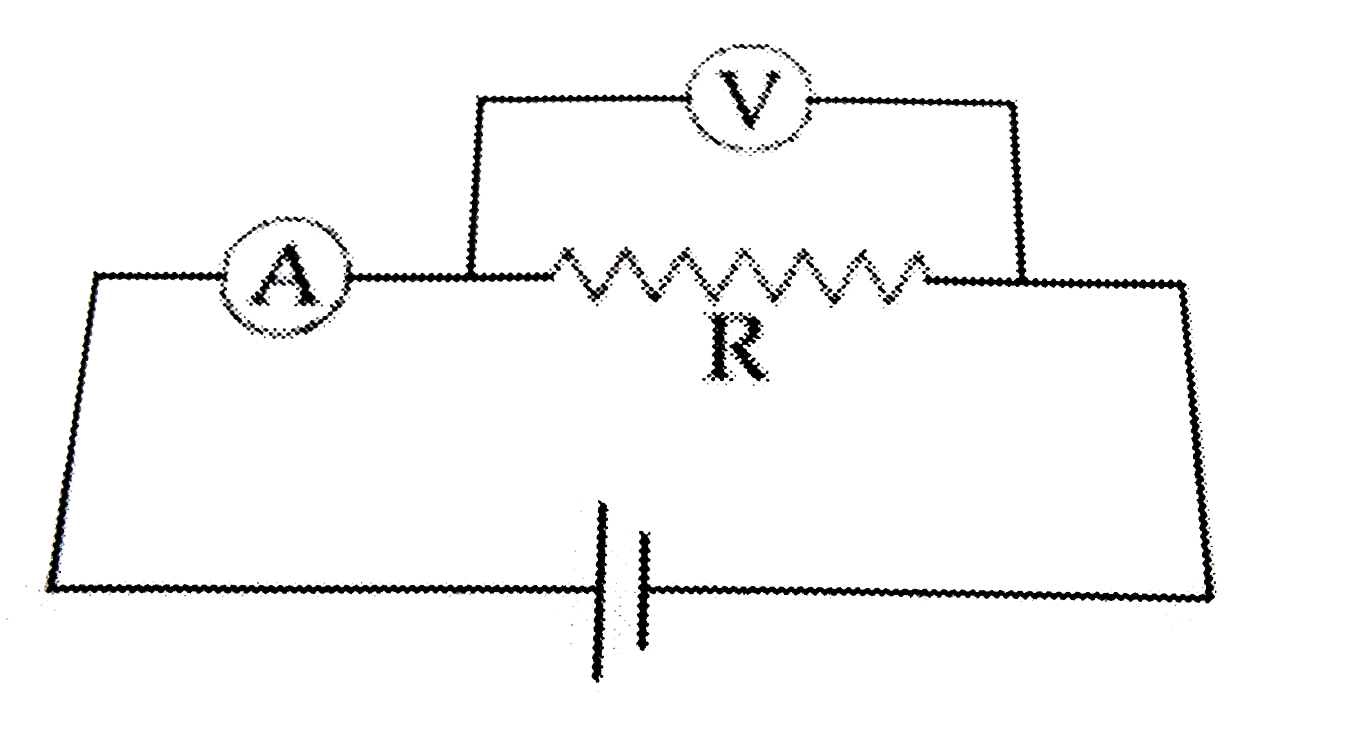
View SolutionThe actual value of resistance R, shown in the figure is 30Ω. This is measured in an experiment as shown using the standard formula R=VI, where V and I are the readings of the voltmeter and ammeter, respectively. If the measured value of R is 5% less, then the internal resistance of the voltmeter is

View Solution
Knowledge Check
For the adjoining circuit diagram, the readings of ammeter and voltmeter are 2A and 120 V respectively. If the value of R is 75Ω, then the voltmeter resistance will be
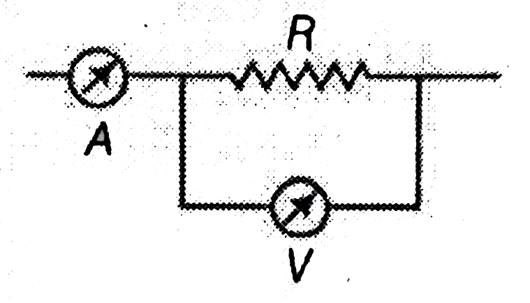 A100ΩB150ΩC300ΩD75Ω
In the adjoining circuit diagram, the readings of ammeter and voltmeter are 2 A and 120 V, respectively. If the value of R is 75Ω, then the voltmeter resistance will be
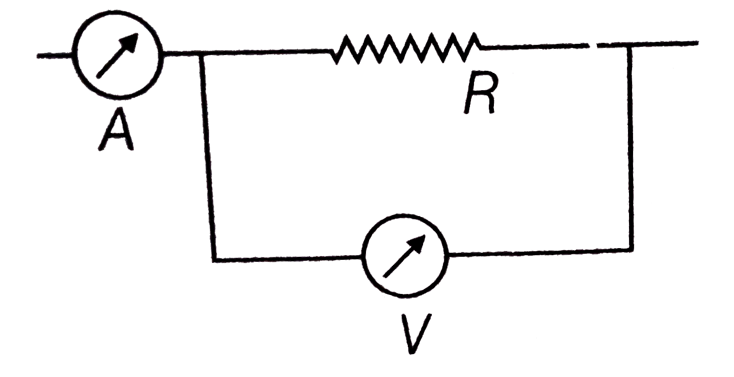 A100ΩB150ΩC300ΩD75Ω
Let V and I be the readings of the voltmeter and the ammeter respectively as shown in the figure. Let RV and RA be their corresponding resistancce Therefore,
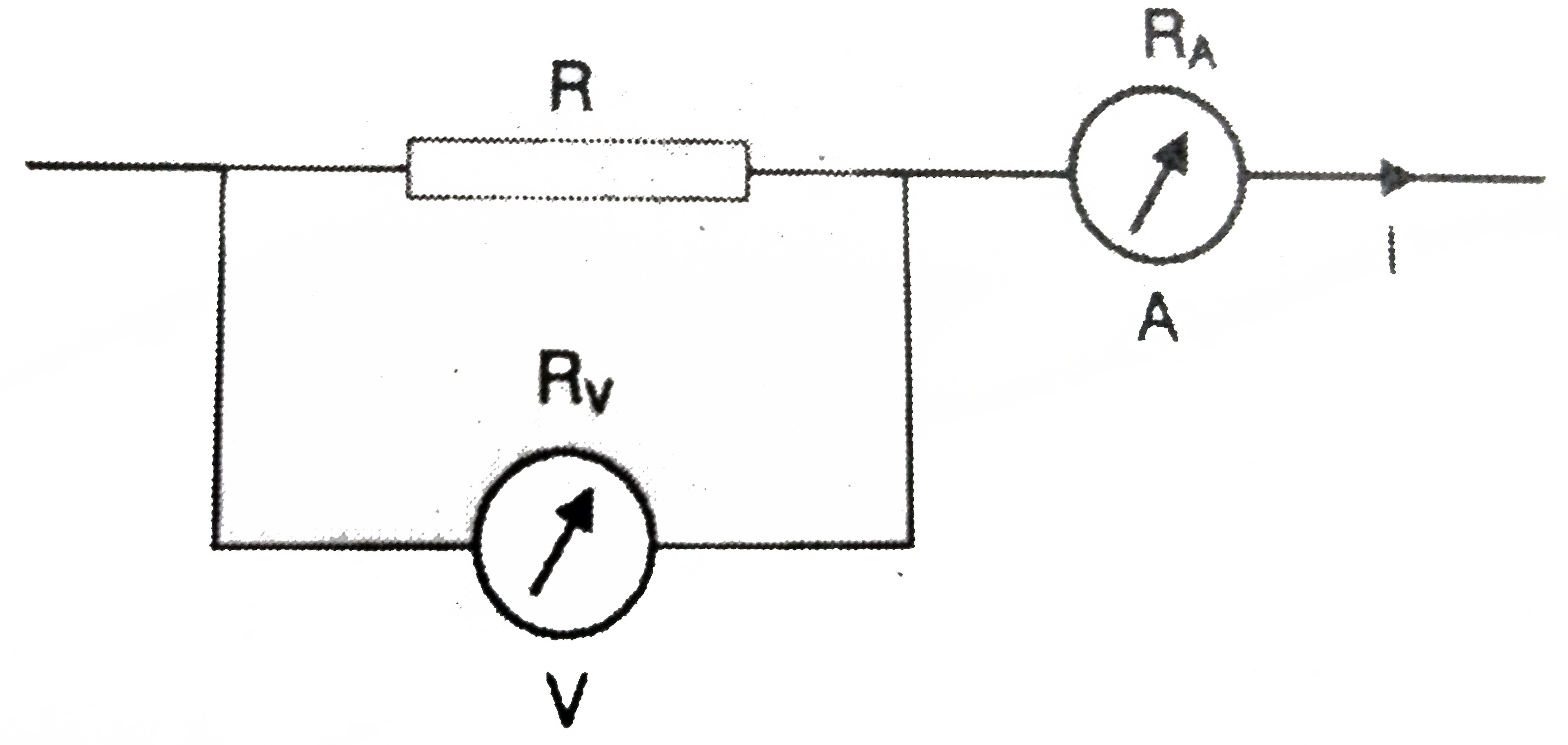 AR=VIBR=VI−(VRV)CR=RV−RADR=V(R+RA)IRA
In the adjoining circuit diagram, the readings of ammeter and voltmeter are 2 A and 120 V, respectively. If the value of R is 75Ω, then the voltmeter resistance will be

View SolutionLet V and I be the readings of the voltmeter and the ammeter respectively as shown in the figure. Let RV and RA be their corresponding resistancce Therefore,

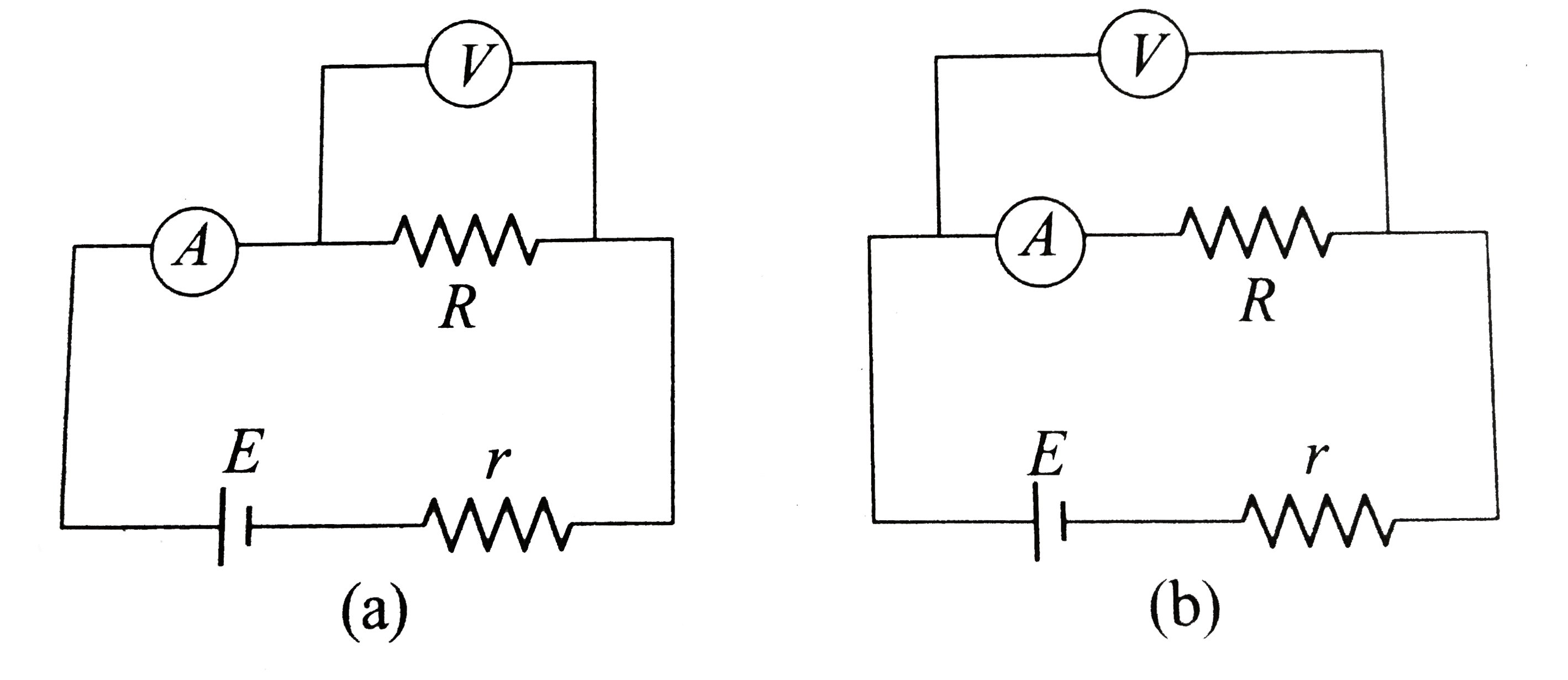
View SolutionThe value of resistance of an unknown resistor is calculated using the formula R=V/I where V and I are the readings of the voltmeter and the ammeter, respectivley. Consider the circuits below. The internal resistances of the voltmeter and the ammeter (RVandRG,respectively) are finite and nonzero.
 ,
,
Let RAandRB be the calculated values in the two cases A and B , respectively.
If the resistance of voltmeter is RV=1kΩ and the percentage error in the measurement of R (the value of R is nearly 10Ω)is
View SolutionThe value of resistance of an unknown resistor is calculated using the formula R=V/I where V and I are the readings of the voltmeter and the ammeter, respectivley. Consider the circuits below. The internal resistances of the voltmeter and the ammeter (RVandRG,respectively) are finite and nonzero.
 ,
,
Let RAandRB be the calculated values in the two cases A and B , respectively.
If the resistance of voltmeter is RV=1kΩ and the percentage error in the measurement of R (the value of R is nearly 10Ω)is
View SolutionThe value of resistance of an unknown resistor is calculated using the formula R=V/I where V and I are the readings of the voltmeter and the ammeter, respectivley. Consider the circuits below. The internal resistances of the voltmeter and the ammeter (RVandRG,respectively) are finite and nonzero.
 ,
,
Let RAandRB be the calculated values in the two cases A and B , respectively.
The relation between RA and the actual value of R is
View Solution
