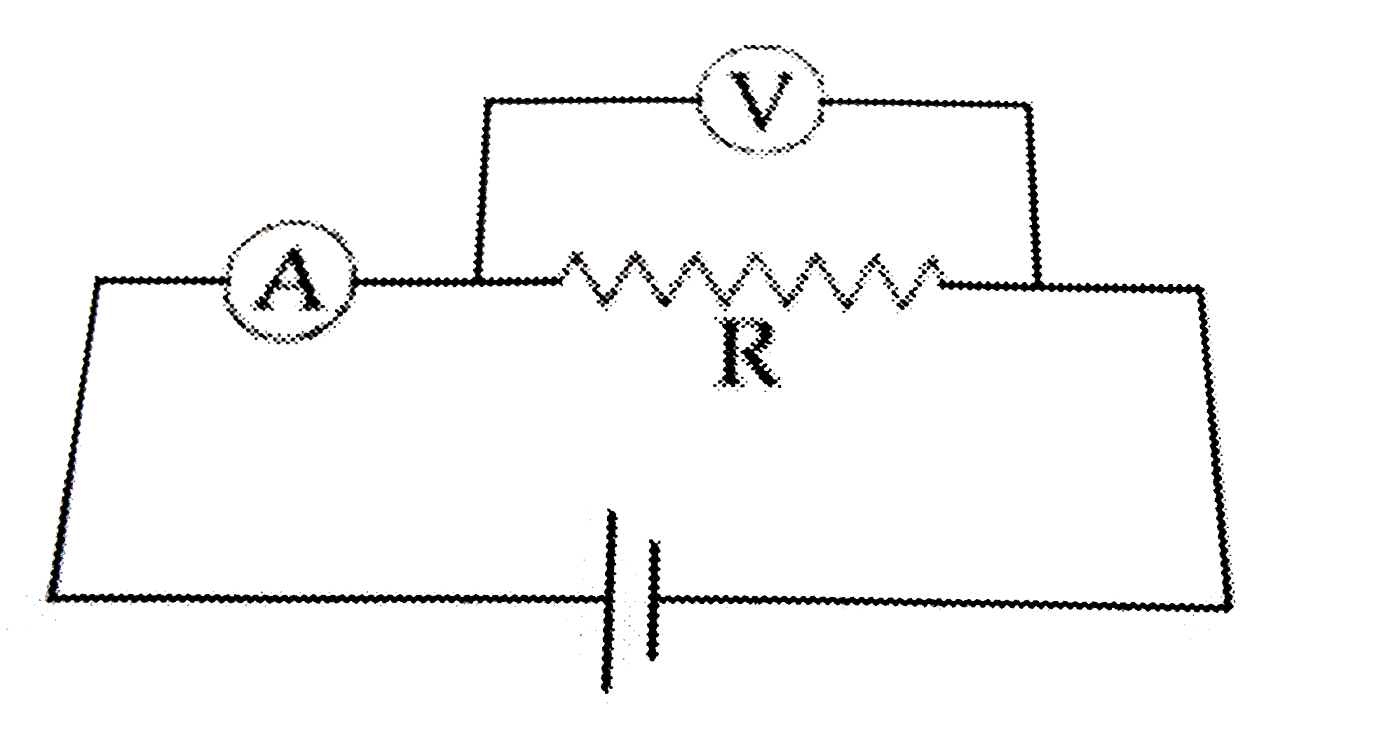
Let V and I be the readings of the voltmeter and the ammeter respectively as shown in the figure. Let RV and RA be their corresponding resistancce Therefore,
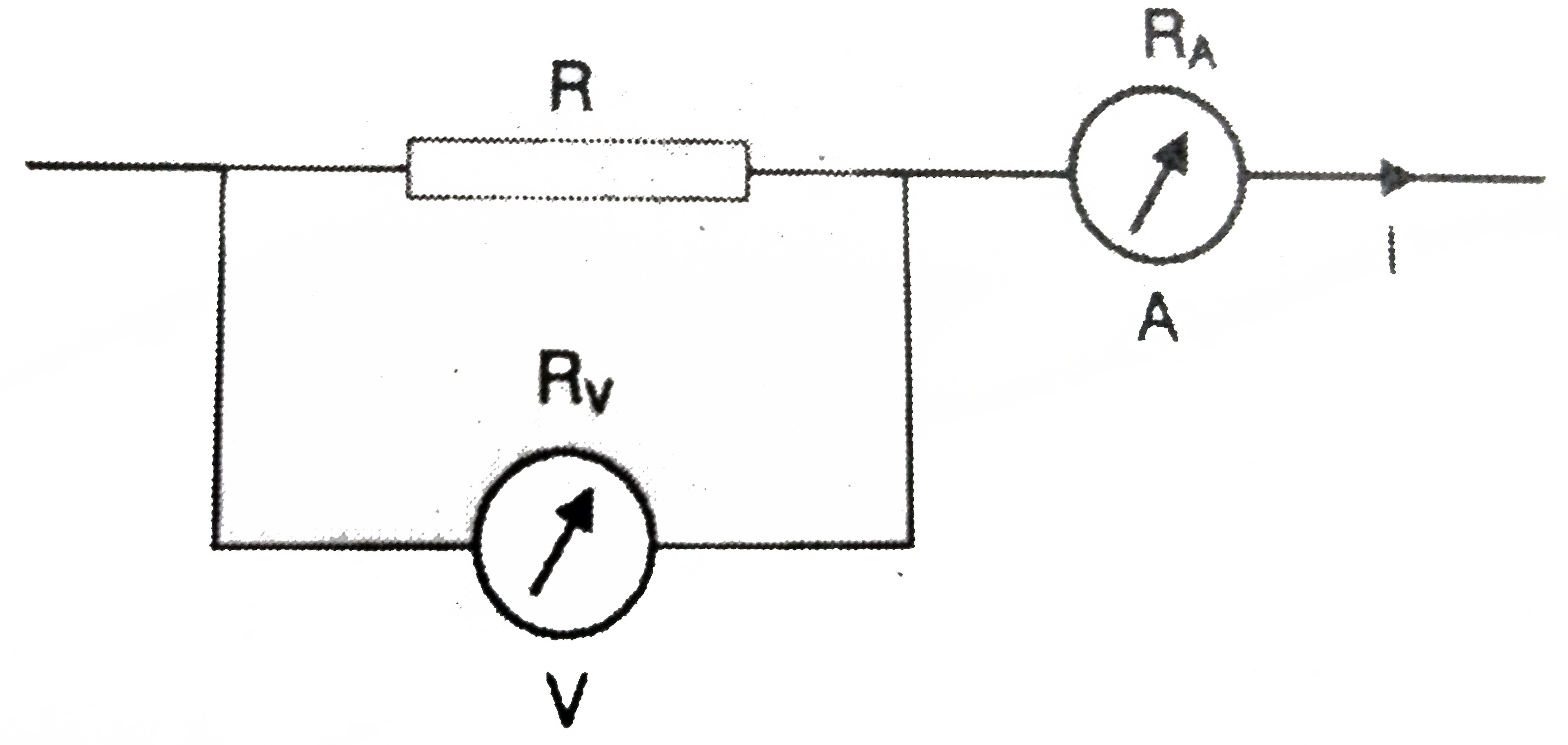
R=VI
R=VI−(VRV)
R=RV−RA
R=V(R+RA)IRA
The correct Answer is:B
Step by step video & image solution for Let V and I be the readings of the voltmeter and the ammeter respectively as shown in the figure. Let R_(V) " and "R_(A) be their corresponding resistancce Therefore, by Physics experts to help you in doubts & scoring excellent marks in Class 12 exams.
Updated on:21/07/2023Topper's Solved these Questions
- CURRENT ELECTRICITYBOOK - RESONANCE ENGLISHCHAPTER - CURRENT ELECTRICITYEXERCISE - Exercise-2 (Part-2)
16 Videos
- CURRENT ELECTRICITYBOOK - RESONANCE ENGLISHCHAPTER - CURRENT ELECTRICITYEXERCISE - Exercise-2 (Part-3)
22 Videos
- CURRENT ELECTRICITYBOOK - RESONANCE ENGLISHCHAPTER - CURRENT ELECTRICITYEXERCISE - Exercise-1 (Part-3)
2 Videos
- COMMUNICATION SYSTEMSBOOK - RESONANCE ENGLISHCHAPTER - COMMUNICATION SYSTEMSEXERCISE - Exercise 3
13 Videos
- DAILY PRACTICE PROBLEMBOOK - RESONANCE ENGLISHCHAPTER - DAILY PRACTICE PROBLEMEXERCISE - DPP.No.71
1 Videos
Similar Questions
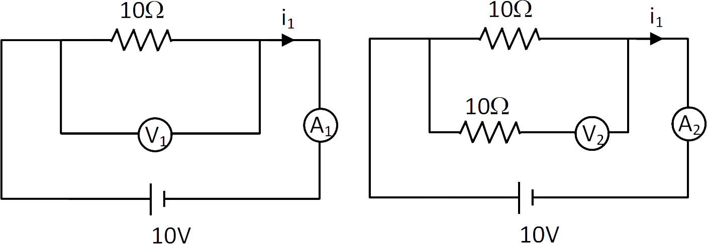
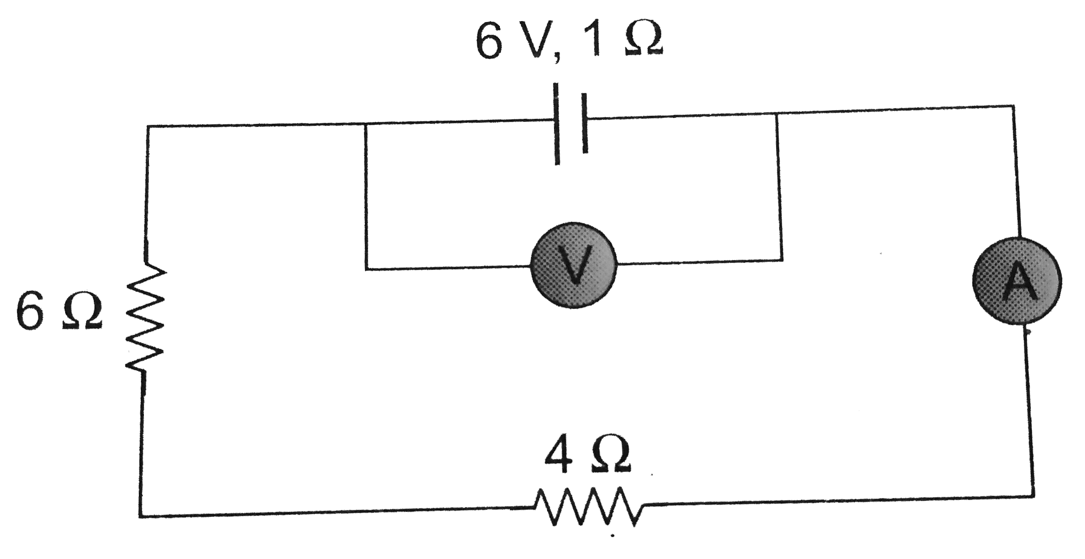
In the circuits shown below, the readings of the voltmeters and the ammeters will be:
View SolutionLet V and I respresent, respectively, the readings of the voltmeter and ammetre shows in Fig. 6.34, and let RV and RV be their equivalent resistances. Because of the resistances of the meters, the resistnce R is not simply equal to V/I.
(a) When the circuit is connected as shows in Fig. 6.34 (a), shows that R=VI−RA
Explain why the true resistance R is always less than V/I.
(b) When the connections are as shows in Fig.6.34 (b)
Show that R=VI−(V/RV)
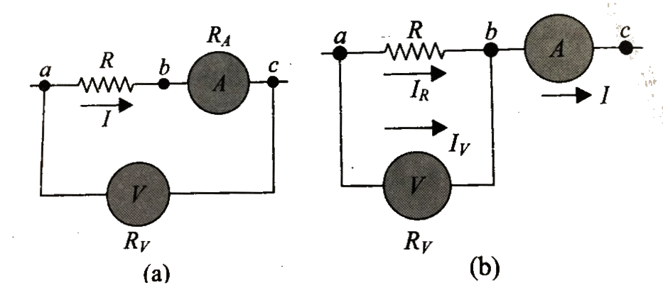
Explain why the true resistance R is always greater than V/I.
(c ) Show that the power delivered to the resistor in part
(i) is IV−I2RA and that in part (ii) is IV−(V2/RV)
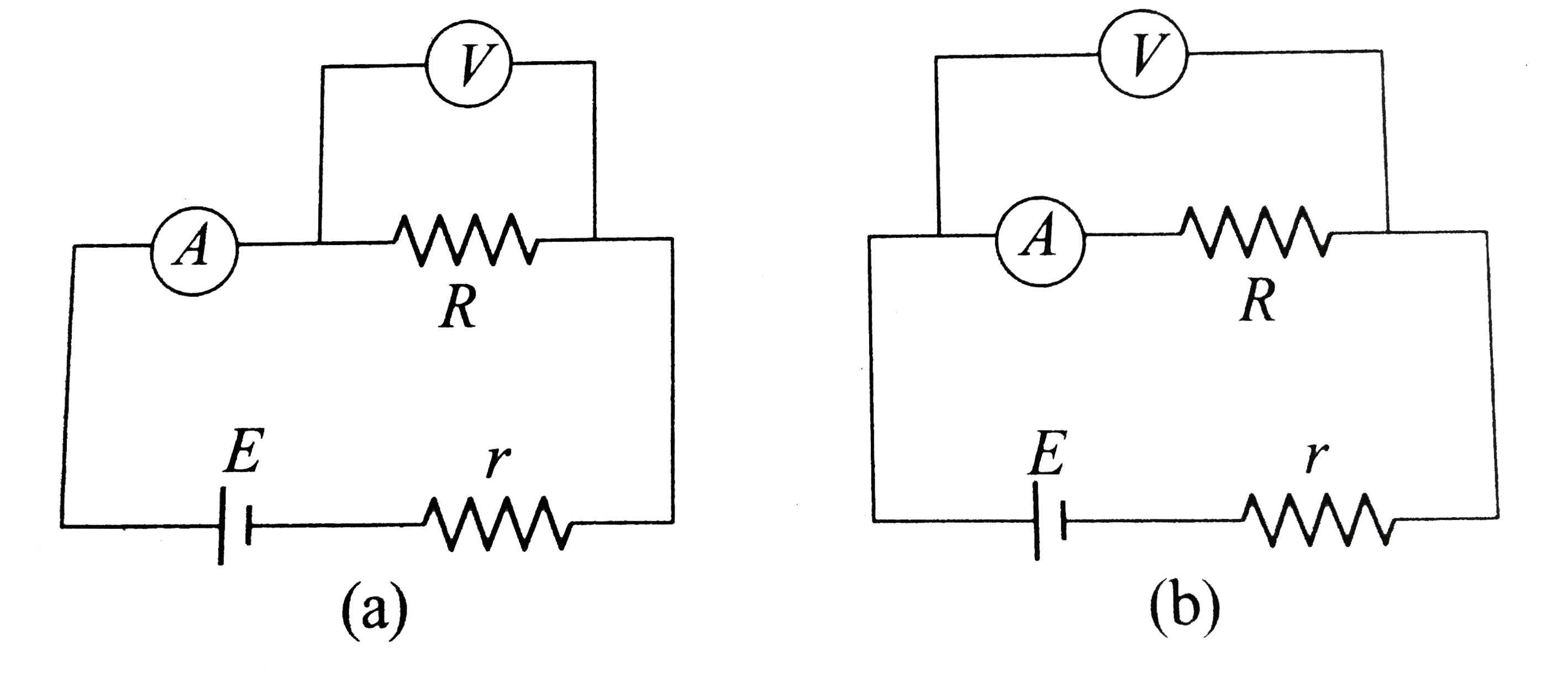
View SolutionThe value of resistance of an unknown resistor is calculated using the formula R=V/I where V and I are the readings of the voltmeter and the ammeter, respectivley. Consider the circuits below. The internal resistances of the voltmeter and the ammeter (RVandRG,respectively) are finite and nonzero.
 ,
,
Let RAandRB be the calculated values in the two cases A and B , respectively.
If the resistance of voltmeter is RV=1kΩ and the percentage error in the measurement of R (the value of R is nearly 10Ω)is
View SolutionThe reading of the A.C voltmeter in the network shown in figure is (where V is in volt)
View SolutionThe actual value of resistance R, shown in the figure is 30Ω. This is measured in an experiment as shown using the standard formula R=VI, where V and I are the readings of the voltmeter and ammeter, respectively. If the measured value of R is 5% less, then the internal resistance of the voltmeter is
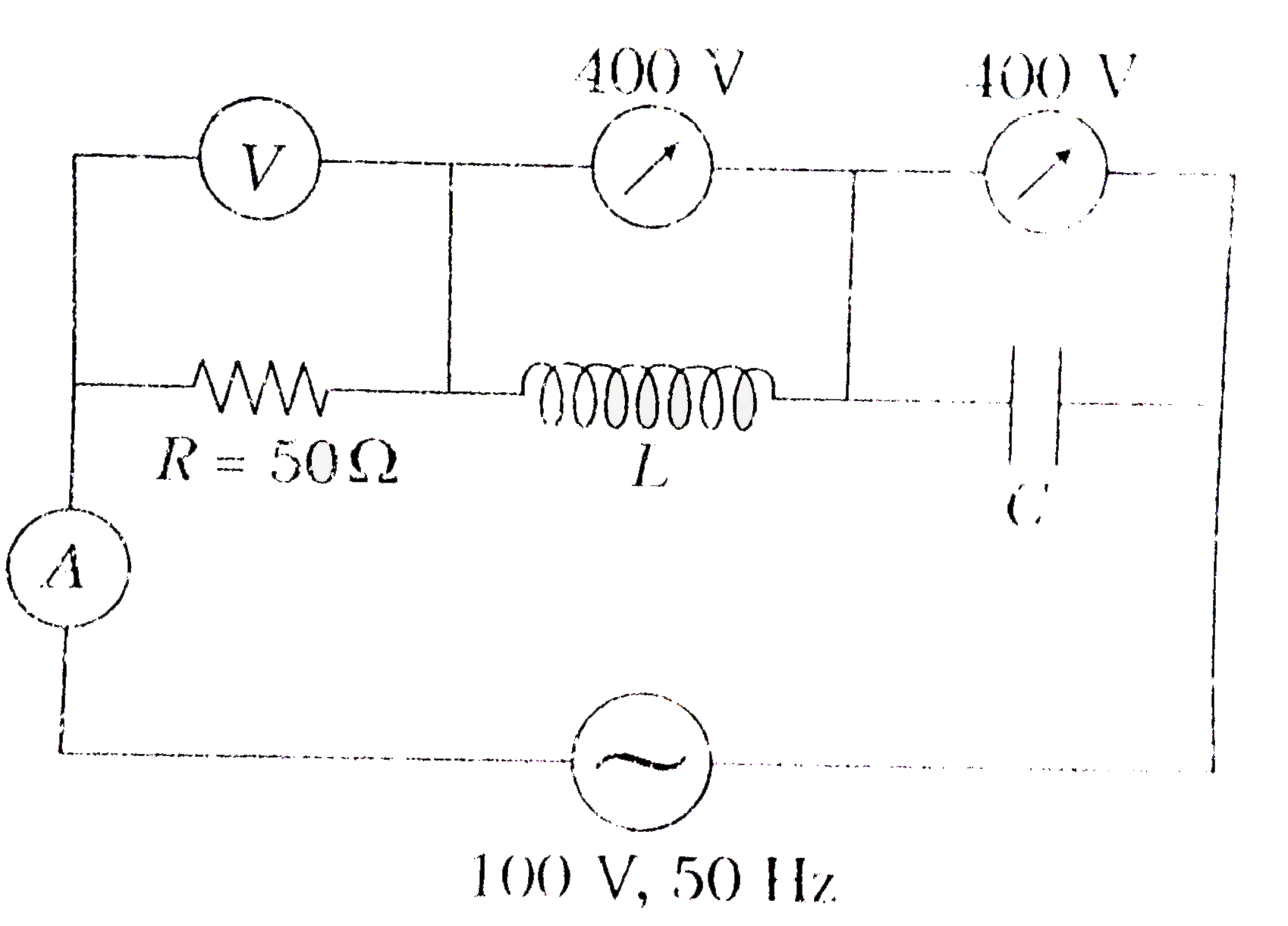
View SolutionIn the series L-C-R circuit , the voltmeter and ammeter readings are
View SolutionIn the series L-C-R circuit , the voltmeter and ammeter readings are

View SolutionThe reading of ammeter and voltmeter in the following circuit are respectively
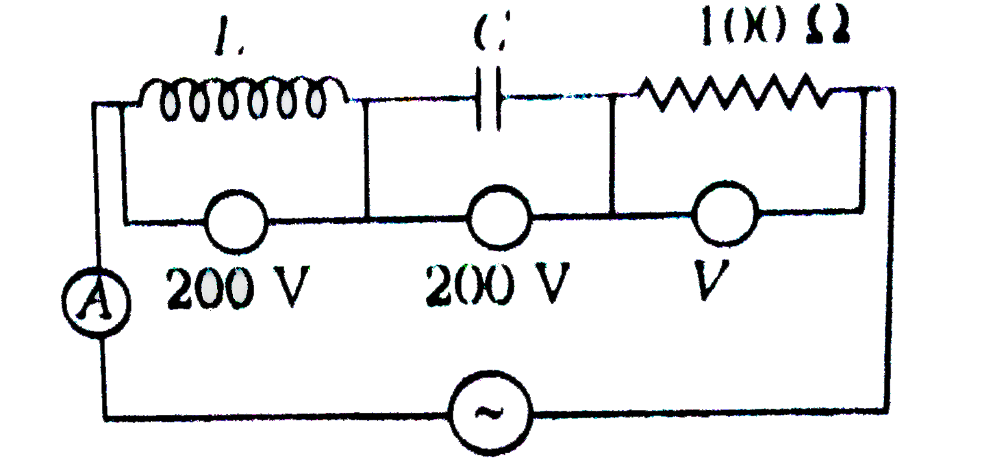
View SolutionIn the series L-C-R circuit , the voltmeter and ammeter readings are respectively
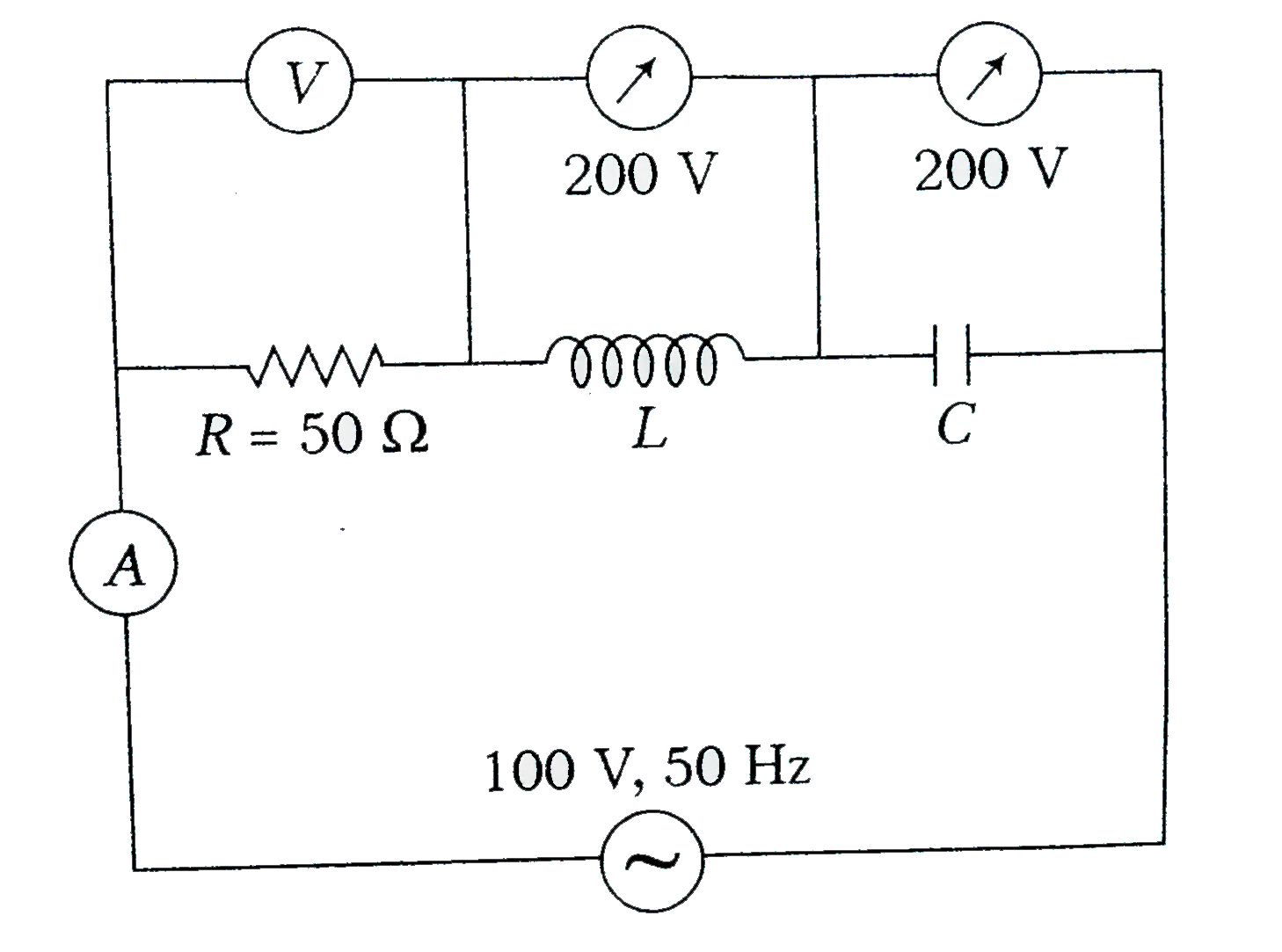
View SolutionIn the circuit shown here, the readings of the ammeter and voltmeter are
View Solution
