In the circuit shown, initially there is no charge on capacitors and keys are open. The values of the capacitors are ,

Which of the following(s) is/are correct?
The keys is kept closed for long time such that capacitors are fully charged. Now, key is closed, at the time, the instantaneous current across resistor (between points P and Q) will be 0.2 A (round off to decimal place)
If key is kept closed for long time such that capacitors are fully charged, the voltage difference between points P and Q will be 10V.
At time t = 0, the key is closed, the instantaneous current in the closed circuit will be 25 mA
If key is kept closed for long time such that capacitors are fully charged, the voltage across the capacitors will be 4 V.
The correct Answer is:C, D
When switch is closed then at t=0 capacitors will act like zero resistance hence instantaneous current at t=0 can be written as
We can see that option (c) is correct. When is kept closed for a long time then capacitors connected in series are charged. Equivalent capacitance of these three can be written as follows:
On solving we get
Charge supplied by the battery .
Potential difference between P and Q is same as potential difference across the capacitor .
.
Hence option (b) is wrong. In Case of steady state there is no current across resistor so potential difference between P and Q (which is equal to 4V) is same as potential difference across capacitor . Hence option (d) is correct.
At t=0 capacitor acts as a battery of potential difference 4V. Capacitors acts like battery of 1/2V each. When is closed then immediately after we can assume capacitor like a zero resistance. Equivalent circuit can be drawn as follows:

We can see that option (a) is wrong.
Topper's Solved these Questions
- CURRENT ELECTRICITYBook:MODERN PUBLICATIONChapter:CURRENT ELECTRICITYExercise:Objective Type Questions (MULTIPLE CHOICE QUESTIONS) (D. MULTIPLE CHOICE QUESTIONS BASED ON A GIVEN PASSAGE/COMPREHENSION)
Explore 15 Videos
- CURRENT ELECTRICITYBook:MODERN PUBLICATIONChapter:CURRENT ELECTRICITYExercise:Objective Type Questions (MULTIPLE CHOICE QUESTIONS) (D. MULTIPLE CHOICE QUESTIONS ASSERTION REASON TYPE QUESTIONS)
Explore 10 Videos
- CURRENT ELECTRICITYBook:MODERN PUBLICATIONChapter:CURRENT ELECTRICITYExercise:Objective Type Questions (MULTIPLE CHOICE QUESTIONS) (B. MULTIPLE CHOICE QUESTION JEE (ADVANCED) FOR IIT ENTRANCE)
Explore 9 Videos
- ATOMS Book:MODERN PUBLICATIONChapter:ATOMS Exercise:Chapter Practice Test
Explore 16 Videos
- DUAL NATURE OF RADIATION AND MATTER Book:MODERN PUBLICATIONChapter:DUAL NATURE OF RADIATION AND MATTER Exercise:CHAPTER PRACTICE TEST
Explore 15 Videos
Similar Questions
Knowledge Check
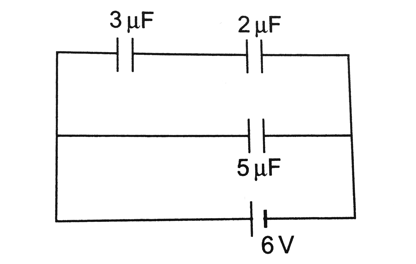
In the circuit shown in figure, the ratio of charge on 5μF and 2μF capacitor is
 A54B53C38Dnone of these
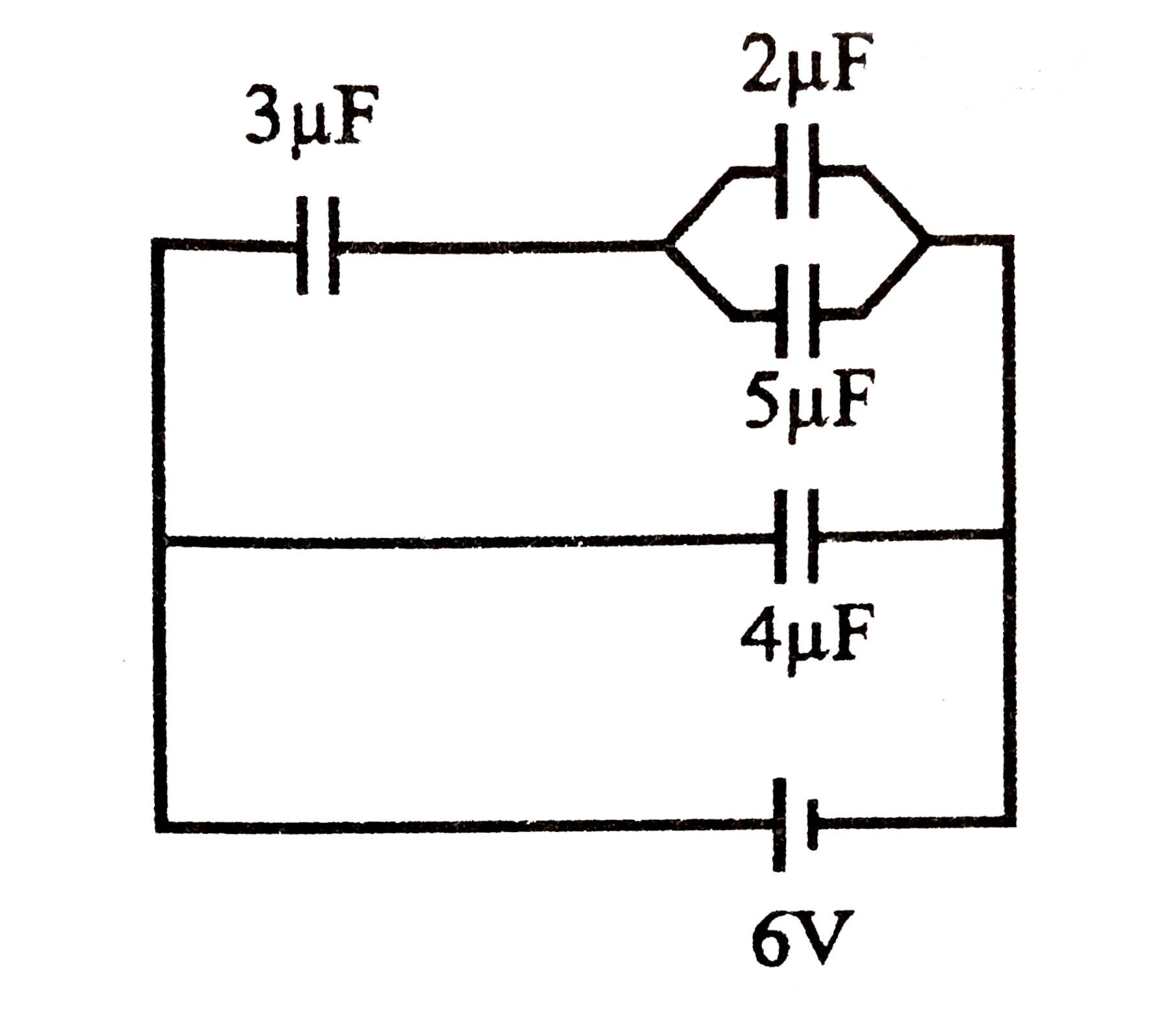
In the circuit shown in figure, the ration of charged on 5μF and 4μF capacitor is-
 A4/5B3/5C3/8D1/2
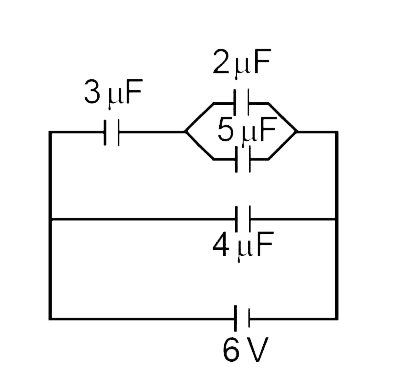
In the circuit shown in figure, the ratio of charges on 5μFand4μF capacitor is :
 A4/5B3/5C3/8D1/2
In the circuit shown the capacitors are C1=15μF,C2=10μFandC3=25μF. Find
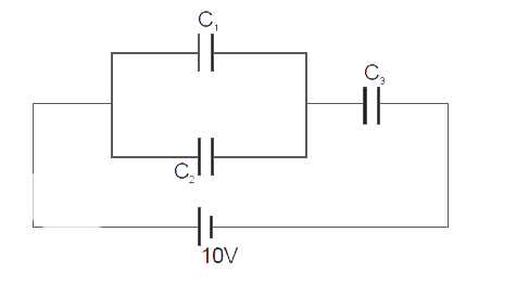
the charge on each capacitor and
View SolutionIn the circuit shown the capacitors are C1=15μF,C2=10μFandC3=25μF. Find
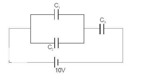
the equivalent capacitance of the circuit.
View SolutionIn the circuit shown the capacitors are C1=15μF,C2=10μFandC3=25μF. Find
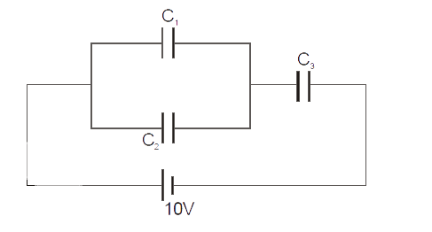
the potential difference across each capacitor.
View SolutionIn the ciruit shown in, C=6μF. The charge stored in the capacitor of capacity C is
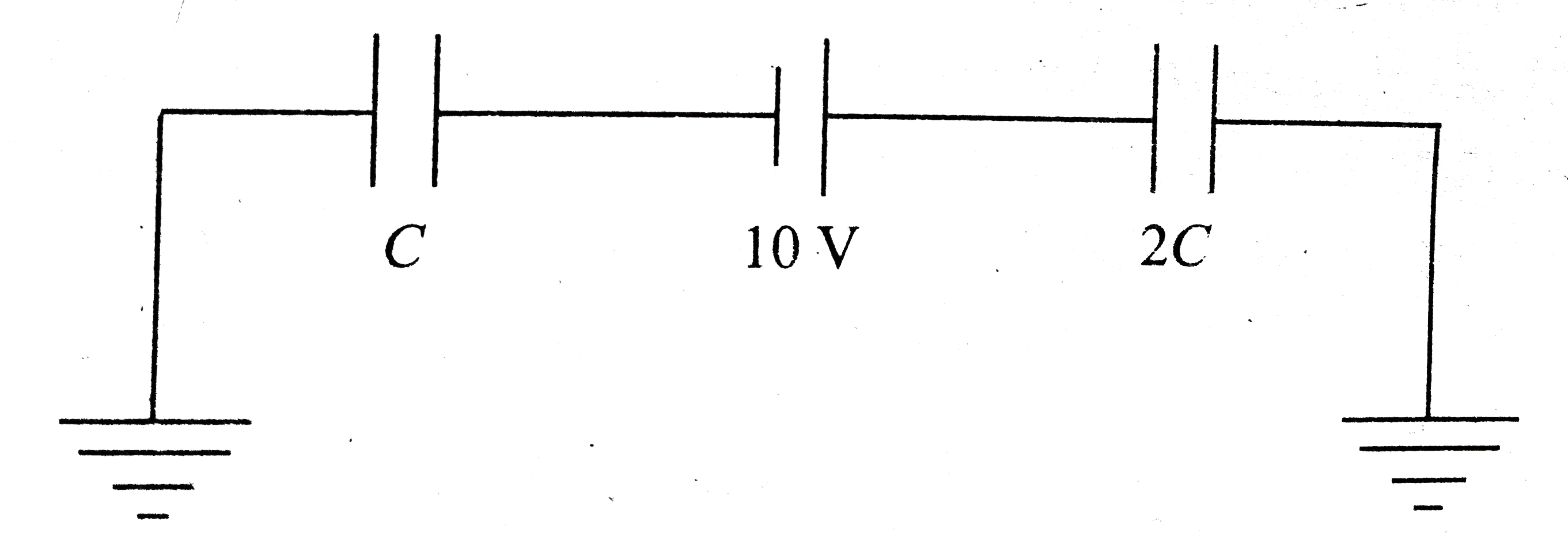 .
.
View SolutionIn the circuit shown in, C=6μF. The charge stored in the capacitor of capacity C is
 .
.
View Solution

