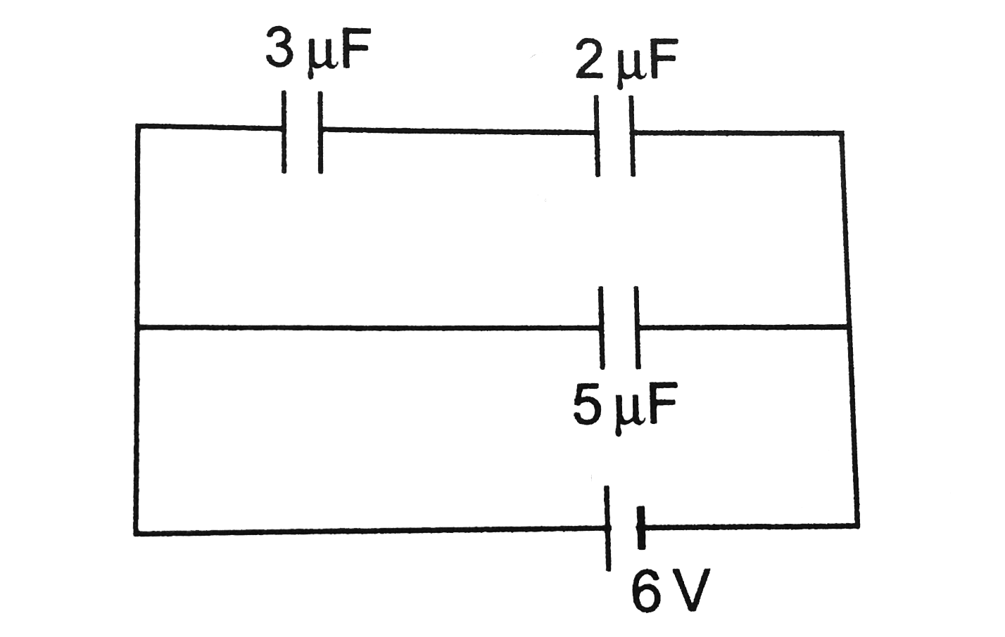
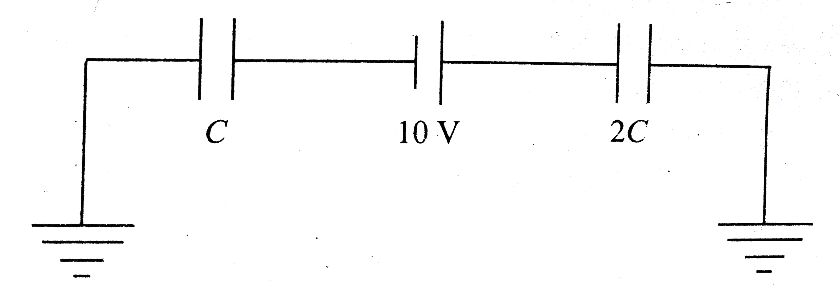
In the circuit shown in figure, the ratio of charge on and capacitor is
none of these
The correct Answer is:D
Topper's Solved these Questions
- BOOK - DC PANDEY ENGLISHCHAPTER - CAPACITORSEXERCISE - OBJECTIVE_TYPE1videos
CAPACITORS
- BOOK - DC PANDEY ENGLISHCHAPTER - CAPACITORSEXERCISE - OBJECTIVE_TYPE1videos
CAPACITORS
- BOOK - DC PANDEY ENGLISHCHAPTER - ATOMSEXERCISE - MEDICAL ENTRANCES GALLERY42videos
ATOMS
- BOOK - DC PANDEY ENGLISHCHAPTER - COMMUNICATION SYSTEMEXERCISE - Subjective11videos
COMMUNICATION SYSTEM
Similar Questions
In the circuit shown in the figure, in steady state:
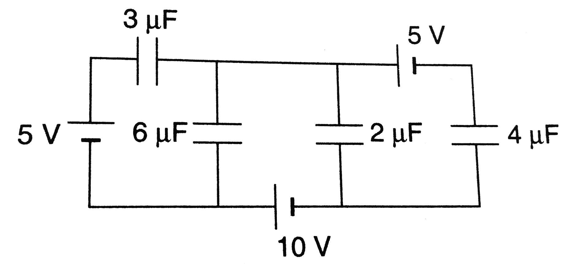
The charge on 5μF capacitor isView SolutionFind the charges on 6μF and 4μF capacitors
 View Solution
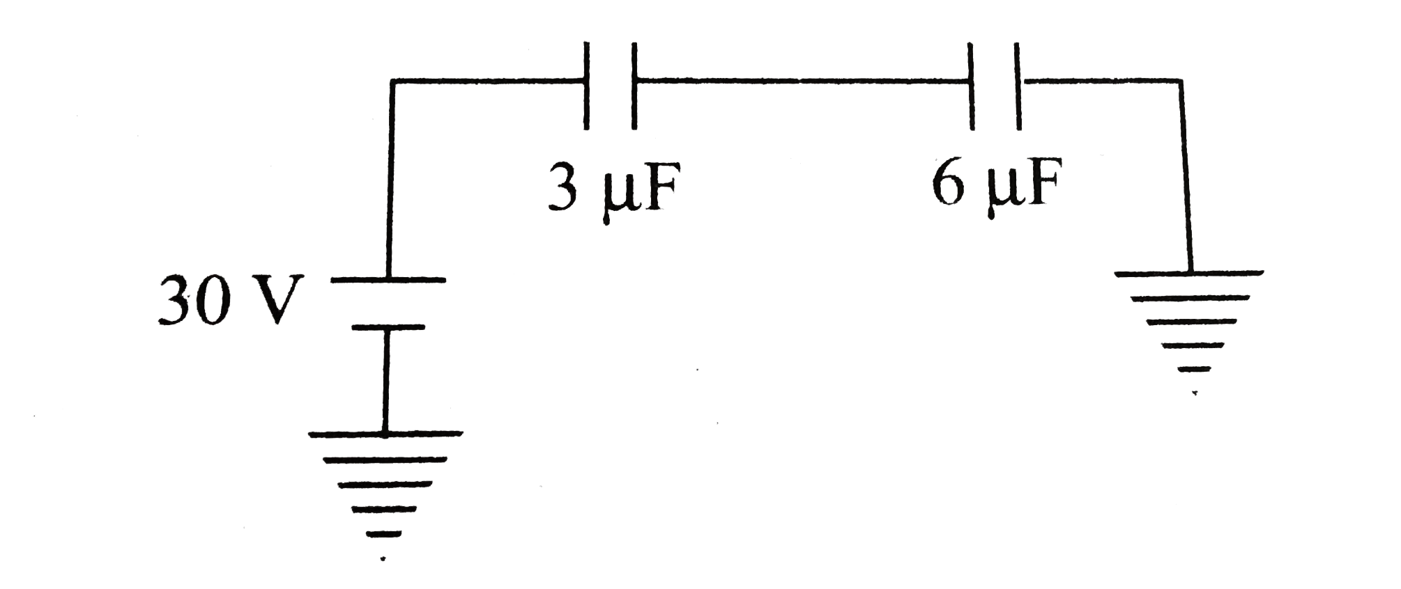
In the circuit shown in figure, the charge stored on a capacitor of capacitance 3μF is
 View Solution
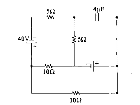
In the circuit shown in figure 3.141, find the energy stored in 4μF capacitor in steady state.
 View Solution
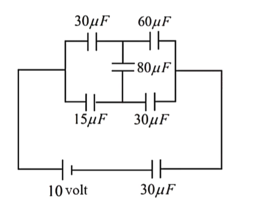
In the circuit shown below, the charge on the 60μF capacitor is
 View Solution
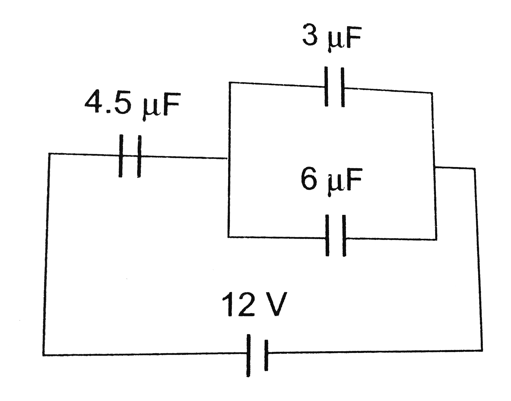
In the circuit shown in the figure, the potential difference across the 4.5μF capacitor is
 View Solution
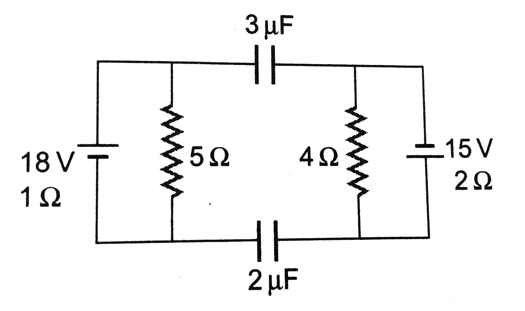
Two cellls, two resistance and two capacitors are connected as shown in figure. The charge on 2μF capacitors is
 View Solution
In the circuit shown in figure charge stored in the capacitor of capacity 5μf is
 View Solution
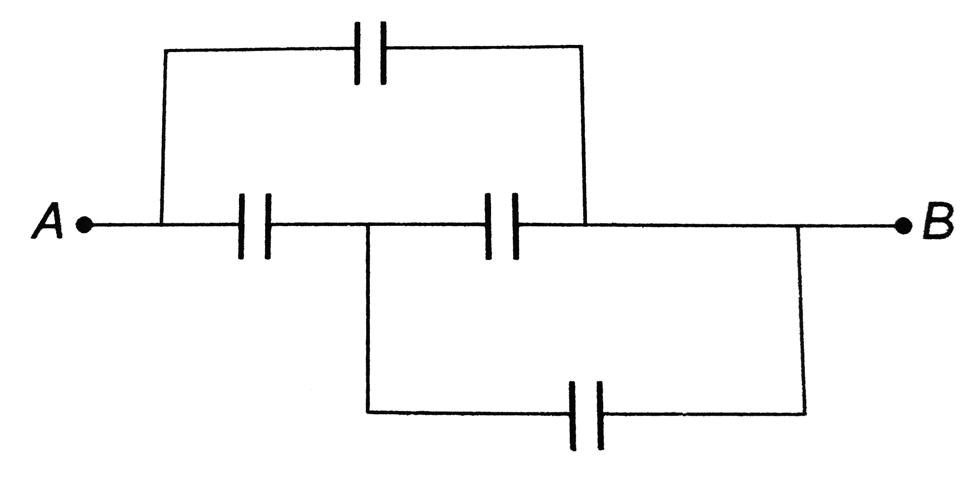
In the circuit shown in figure, each capacitor has a capacity of 3μF. The equivalent capacity between A and B is
 View Solution
In the ciruit shown in, C=6μF. The charge stored in the capacitor of capacity C is
 . View Solution

