In the circuit shown, inputs A and B are in states '1' and '0' respectively. What is the only possible stable state of the outputs 'X' and 'Y'?
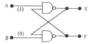
X = '1', 'Y' = '1'
X = '1', 'Y' = '0'
X = '0', 'Y' = '1'
X = '0', 'Y' = '0'
Step by step video & image solution for In the circuit shown, inputs A and B are in states '1' and '0' respectively. What is the only possible stable state of the outputs 'X' and 'Y'? by Physics experts to help you in doubts & scoring excellent marks in Class 12 exams.
Updated on:21/07/2023Topper's Solved these Questions
- SOLID STATE ELECTRONS BOOK - MTG-WBJEECHAPTER - SOLID STATE ELECTRONS EXERCISE - WB JEE WORKOUT (CATEGORY 3 : One or More than one option Correct Type)
10 Videos
- PARTICLE NATURE OF LIGHT AND WAVE PARTICLE DUALISMBOOK - MTG-WBJEECHAPTER - PARTICLE NATURE OF LIGHT AND WAVE PARTICLE DUALISMEXERCISE - WB JEE PREVIOUS YEARS QUESTIONS
15 Videos
- THERMODYNAMICSBOOK - MTG-WBJEECHAPTER - THERMODYNAMICSEXERCISE - WB JEE Previous Years Questions
12 Videos
Similar Questions
In the logic circuit shown in the figure, if input A and B are 0 to 1 respectively, the output at Y would be ‘x’
The value of x is _______

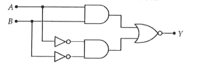
View SolutionIn the given circuit, the binary inputs at A and B are both 1 in one case and both 0 in the next case. The respective outputs at Y in these two cases will be:
View Solution
Knowledge Check
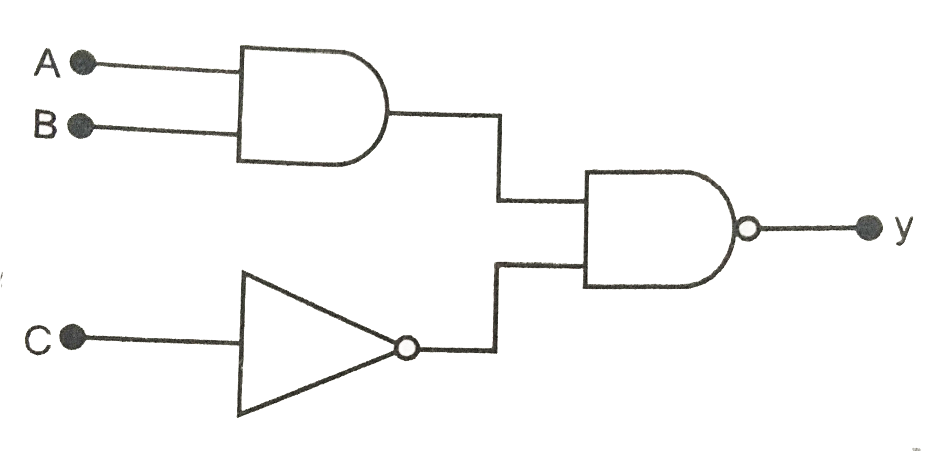
In the circuit givne, A, B and C are inputs and Y is the output.

The output of Y isAhigh for all the high inputsBhigh for all the low inputsChigh when A=1,B=1,C=0Dlow for all low inputsThe output of a two input NOR gate is in state 1 when :-
Aeither input terminals is at 0 stateBeither input terminals is at 1 stateCboth input terminals are at 0 stateDboth input terminals are at 1 stateLet inputs of p and q be 1 and 0 respectively in electric circuit . Then output of p∧q is
A1B0CBoth 1 and 0DNeither 1 nor 0

The output y, when all three inputs are first high and then low, will respectively be
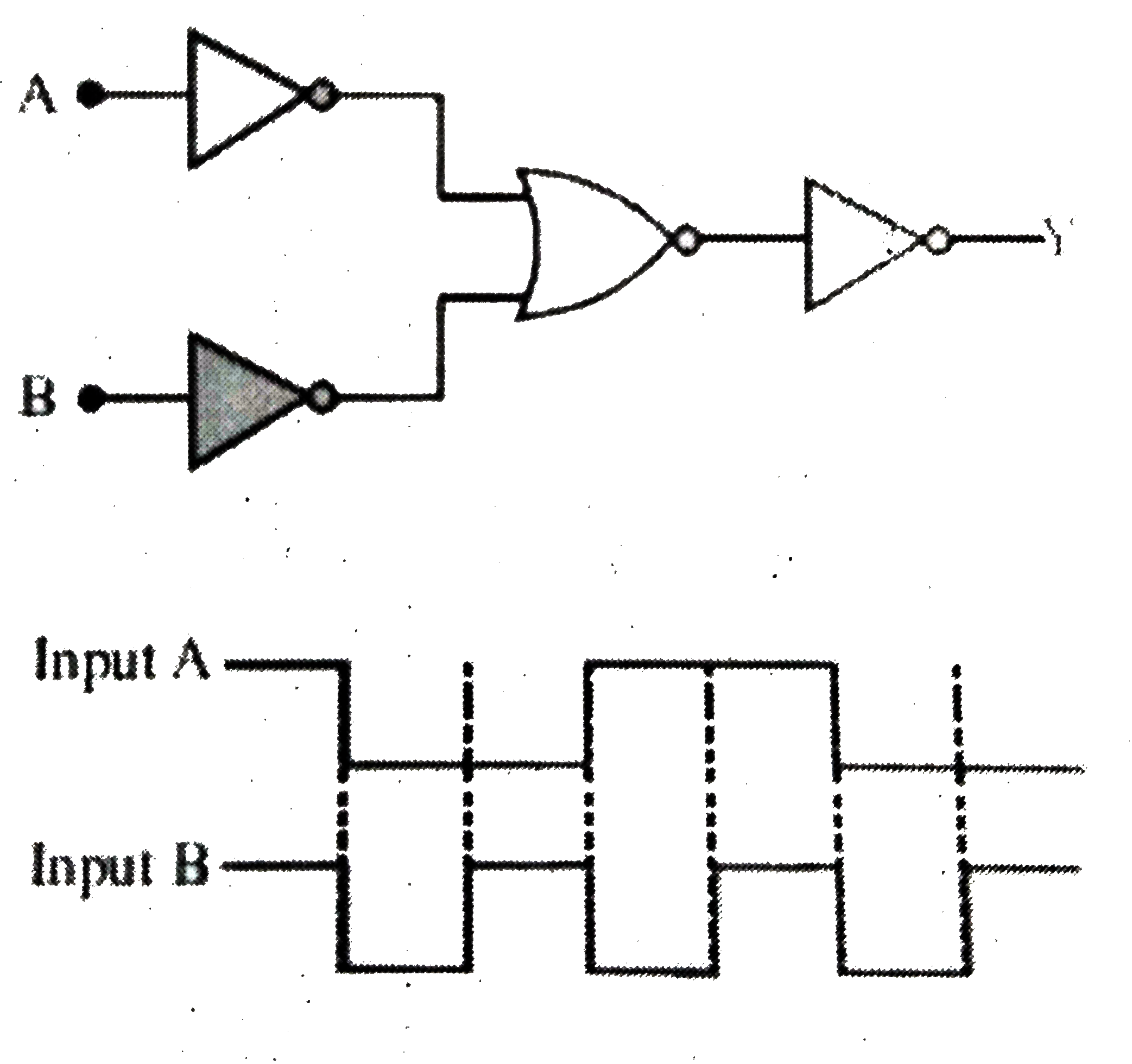
View SolutionThe logic circuit shown has the input waveforms 'A' and 'B' as shown. Pick out the correct output waveform
View SolutionIn AND gate, the output Y is 1 when the inputs A and B are:
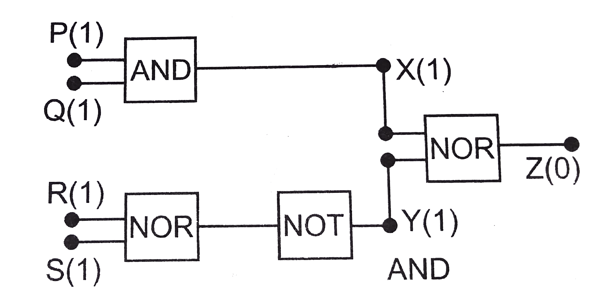
View SolutionThe circuit diagram (see fig.) shows a 'logic combination' with the states outputs X,Y and Z given for input P,Q,R and S all at state 1 (i.e., high). When inputs P and R change to state 0 i.e., low) with inputs Q and S still at 1, the condition of output X,Y and Z chages to
View SolutionIn the circuit Fig. the output y becomes zero for the inputs
View Solution
