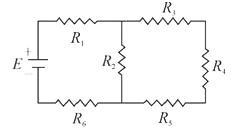
Find the output of the ideal operational amplifier shown in the figure for each of the following input signals
data:Rf=39KΩ,R1=15kΩ

Text Solution
The gain of the amplifier Av=−RfRIn=−39×10315×103
=−2.6
V0=−2.6[(0.8sinωt+75∘)V]
=−2.08sin(ωt+75∘)V
|
Topper's Solved these Questions
- SEMI-CONDUCTORS ELECTRONICSBOOK - OSWAAL PUBLICATIONCHAPTER - SEMI-CONDUCTORS ELECTRONICSEXERCISE - TOPIC -4 LOGIC GATES (VERY SHORT ANSWER TYPE QUESTIONS)
3 Videos
- SEMI-CONDUCTORS ELECTRONICSBOOK - OSWAAL PUBLICATIONCHAPTER - SEMI-CONDUCTORS ELECTRONICSEXERCISE - TOPIC -4 LOGIC GATES (SHORT ANSWER TYPE QUESTIONS-I)
14 Videos
- SEMI-CONDUCTORS ELECTRONICSBOOK - OSWAAL PUBLICATIONCHAPTER - SEMI-CONDUCTORS ELECTRONICSEXERCISE - TOPIC -3 TRANSISTORS AND THEIR APPLICATIONS (LONG ANSWER TYPE QUESTIONS-)
10 Videos
- Sample Paper 8BOOK - OSWAAL PUBLICATIONCHAPTER - Sample Paper 8EXERCISE - Exercise
37 Videos
- SOLVED PAPER (II PUC JULY 2016)BOOK - OSWAAL PUBLICATIONCHAPTER - SOLVED PAPER (II PUC JULY 2016)EXERCISE - PART D
11 Videos
Similar Questions
Knowledge Check

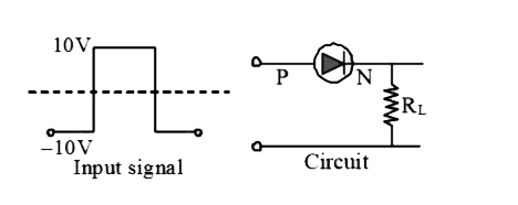
In p-n junction diode a square input signal of 10 V is applied as shown in figure The output signal across RL will beA B
B C
C D
D

In p-n junction diode a square input signal of 10 V is applied as shown in figure The output signal across RL will beA B
B C
C D
D
In the circuit shown in the diagram, the operational amplifier may be assumed to be ideal. The current in the 12kΩ resistor is I.
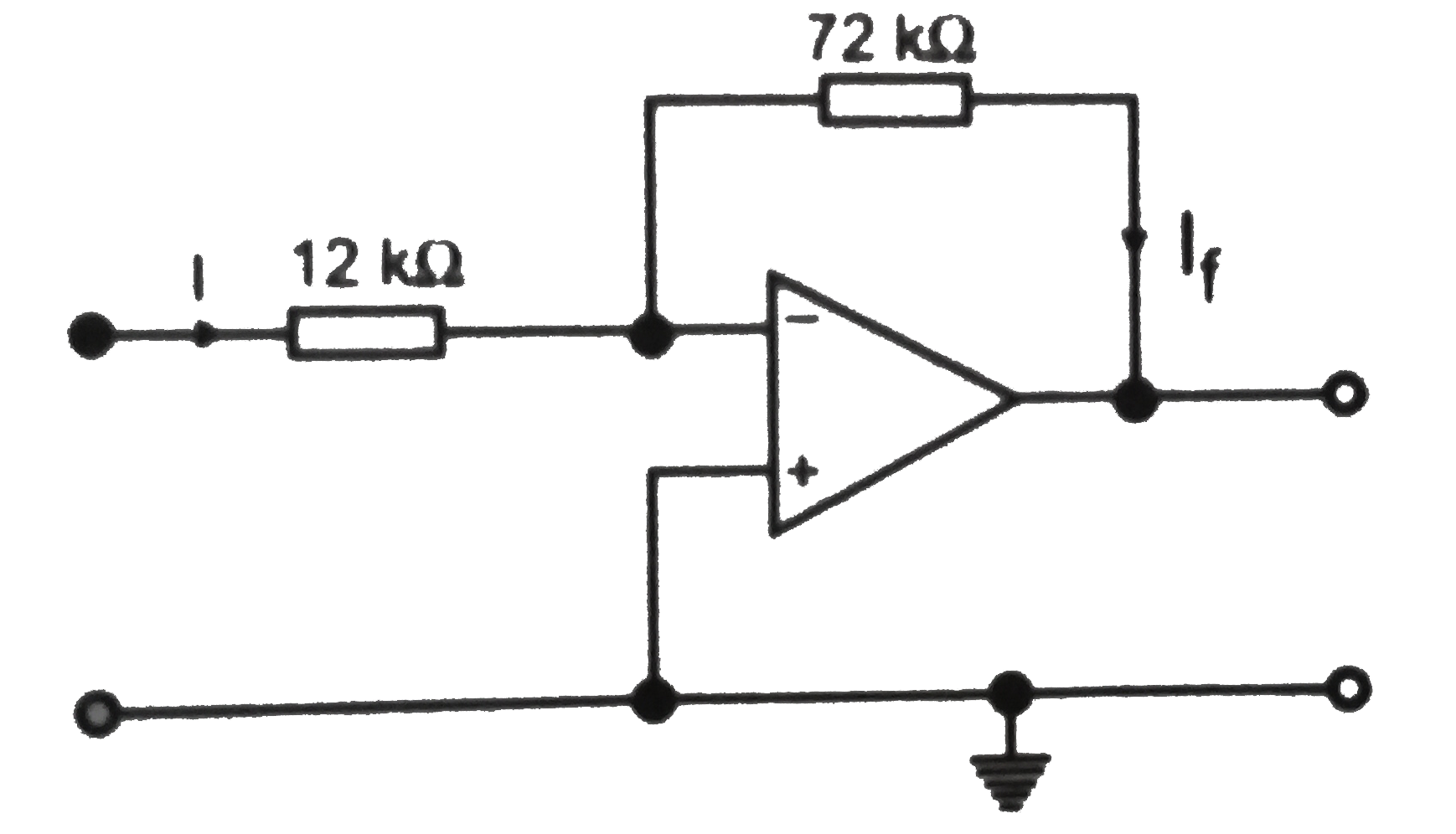
What is the current If in the 72kΩ resistor?A−6BIC−1/6ID6I
If in a p - n junction diode , a square input signal of 10 V is applied as shown
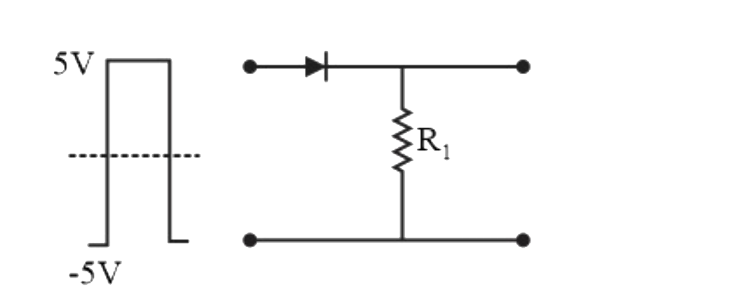
Then the output signal across RL will be
View SolutionIf in a p - n junction diode , a square input signal of 10 V is applied as shown
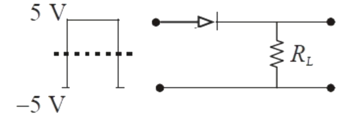
Then the output signal across RL will be
View SolutionIf the following input signal is sent through a P-N junction diode, then the output signal across RL will be -
View SolutionWhich of the following figures correctly shows the phase relation between the input signal and the output signal of triode amplifier
View SolutionIf a pn junction dide, a square input signal of 10 V is applied as shown

then the outuput signal across R1 will be
View Solution

