Find the output of the ideal operational amplifier shown in the figure for each of the following input signals
VIn=120mVdC

The gain of the amplifier Av=−RfRIn=−39×10315×103
=−2.6
out put of the OP.AMP(V0)=−RfRIn×V)(In)
=−2.6×120×10−3=−0.312V
Topper's Solved these Questions
- SEMI-CONDUCTORS ELECTRONICSBOOK - OSWAAL PUBLICATIONCHAPTER - SEMI-CONDUCTORS ELECTRONICSEXERCISE - TOPIC -4 LOGIC GATES (VERY SHORT ANSWER TYPE QUESTIONS)
3 Videos
- SEMI-CONDUCTORS ELECTRONICSBOOK - OSWAAL PUBLICATIONCHAPTER - SEMI-CONDUCTORS ELECTRONICSEXERCISE - TOPIC -4 LOGIC GATES (SHORT ANSWER TYPE QUESTIONS-I)
14 Videos
- SEMI-CONDUCTORS ELECTRONICSBOOK - OSWAAL PUBLICATIONCHAPTER - SEMI-CONDUCTORS ELECTRONICSEXERCISE - TOPIC -3 TRANSISTORS AND THEIR APPLICATIONS (LONG ANSWER TYPE QUESTIONS-)
10 Videos
- Sample Paper 8BOOK - OSWAAL PUBLICATIONCHAPTER - Sample Paper 8EXERCISE - Exercise
37 Videos
- SOLVED PAPER (II PUC JULY 2016)BOOK - OSWAAL PUBLICATIONCHAPTER - SOLVED PAPER (II PUC JULY 2016)EXERCISE - PART D
11 Videos
Similar Questions
If in p-n junction diode a sinusoidal input signal is applied as shown Then the output signal across RL will bw
View SolutionTwo amplifiers are connected one after the other in series. The first amplifier has a voltage gain of 10 and the second has a voltage gain of 20. If the input signal is 0.012 volt then output signal (in V)?
View Solution
Knowledge Check
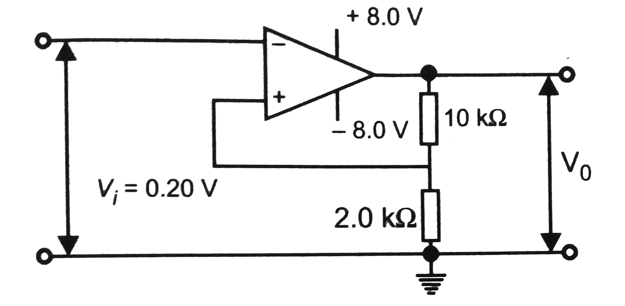
An input voltage Vi of 0.20V is applied to an operational amplifier connected as shown in the diagram. What is the output voltage V0?
 A0.20VB1.2VC0.80VD8.0V
In p-n junction diode a square input signal of 10 V is applied as shown in figure The output signal across RL will beA B
B C
C D
D

In p-n junction diode a square input signal of 10 V is applied as shown in figure The output signal across RL will beA B
B C
C D
D
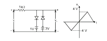
The figure below shows a circuit and its input voltage vi as function of time t.

Assuming the diodes to be ideal, which of the following graphs depicts the output voltage v0 as function of time t ?
View SolutionWhen a transistor amplifier having current gain of 75 is given an input signal, VI=2sin(157t+π/2), the output signal is found to be Vo=200sin(157t+3π/2). The transistor is connected as :
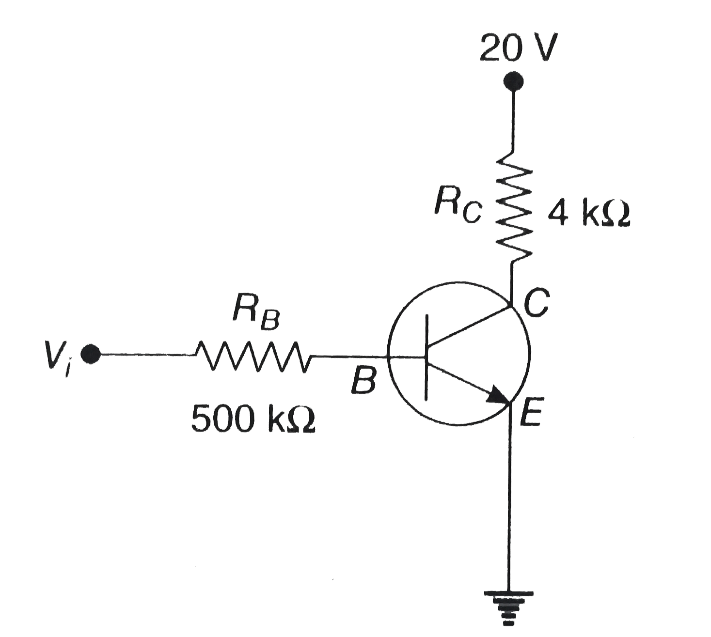
View SolutionIn the circuit shown in the figure, the input voltage Vi is 20V,VBE=0 and VCE=0. The values of IB,IC and β are given by:

View SolutionWhich of the following figures correctly shows the phase relation between the input signal and the output signal of triode amplifier
View SolutionIn a common emitter amplifier, using output reisistance of 5000 ohm and input resistance fo 2000ohm, if the peak value of input signal voltage is 10mV and β=50, then the peak value of output voltage is
View Solution
