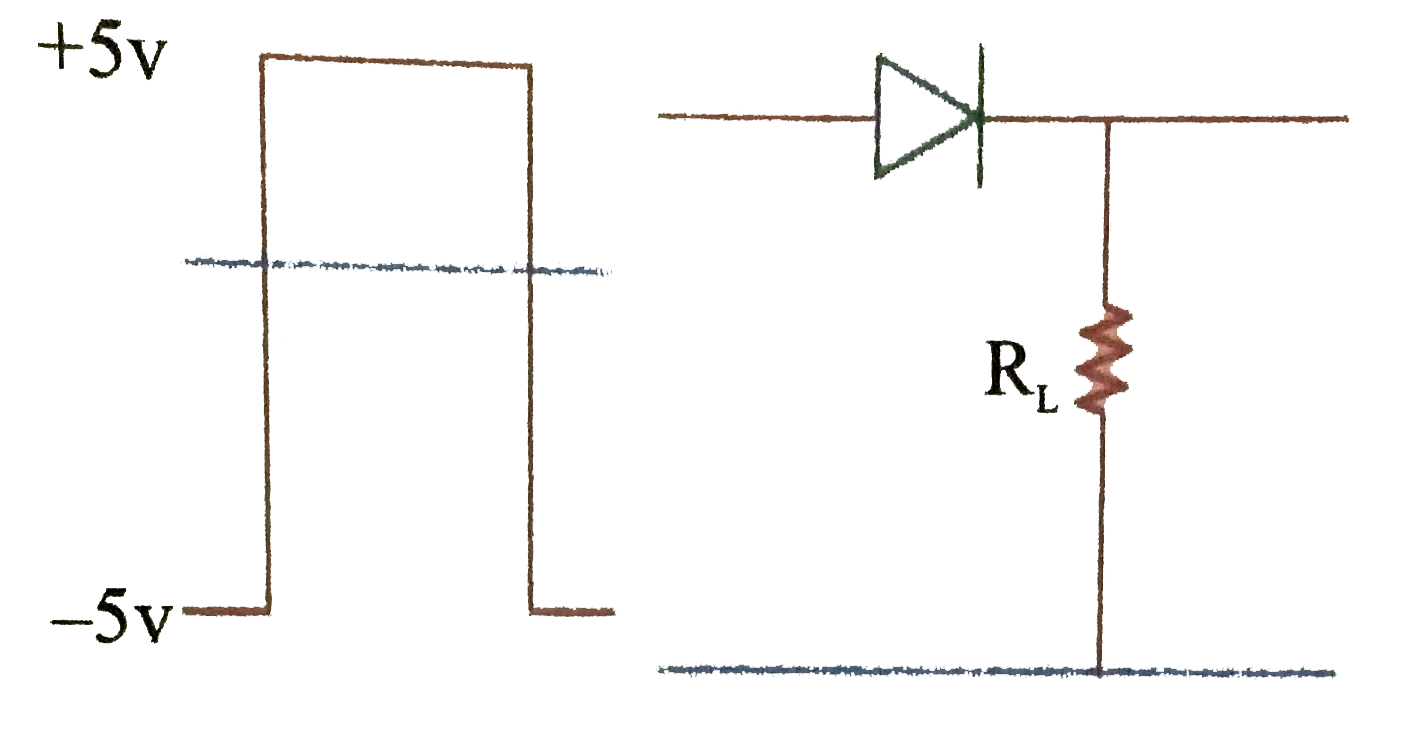
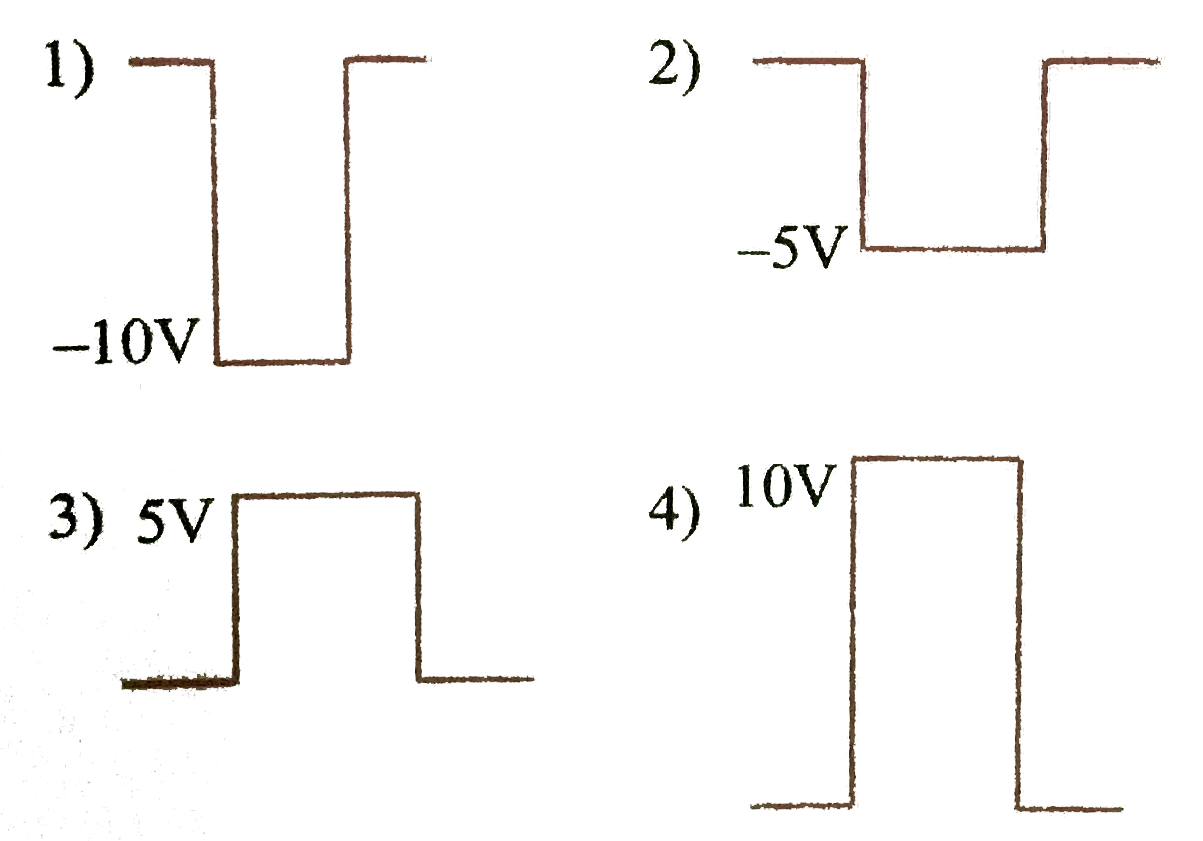
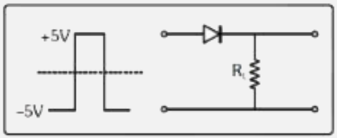
If in p-n junction diode a sinusoidal input signal is applied as shown Then the output signal across RL will bw
To determine the output signal across the load resistor RL when a sinusoidal input signal is applied to a p-n junction diode, we can follow these steps:
1. Understand the Input Signal:
The input signal is a sinusoidal AC voltage. This means the voltage varies in a sine wave pattern over time, oscillating between positive and negative values.
2. Identify the Function of the p-n Junction Diode:
The p-n junction diode allows current to flow in one direction (forward bias) and blocks current in the reverse direction (reverse bias). This characteristic is crucial for rectification.
3. Analyze the Output Across the Load Resistor RL:
When the sinusoidal AC signal is applied to the diode:
- During the positive half-cycle of the AC signal, the diode is forward-biased, allowing current to flow through the diode and RL. This results in a positive voltage across RL.
- During the negative half-cycle of the AC signal, the diode is reverse-biased, preventing current from flowing. Therefore, there is no voltage across RL during this period.
4. Resulting Output Waveform:
The output across RL will consist of only the positive half-cycles of the input sinusoidal waveform. This results in a waveform that has only positive spikes, corresponding to the times when the diode is conducting. The output can be described as a pulsating DC signal.
5. Sketch the Output Waveform:
The output waveform can be sketched as a series of positive spikes (representing the forward-biased conduction of the diode) with zero voltage during the negative half-cycles. This is often referred to as a "pulsating DC" signal.
Final Output Signal Description:
The output signal across RL will be a pulsating DC waveform, consisting of positive voltage spikes corresponding to the positive half-cycles of the input AC signal.
---
The input signal is a sinusoidal AC voltage. This means the voltage varies in a sine wave pattern over time, oscillating between positive and negative values.
The p-n junction diode allows current to flow in one direction (forward bias) and blocks current in the reverse direction (reverse bias). This characteristic is crucial for rectification.
When the sinusoidal AC signal is applied to the diode:
- During the positive half-cycle of the AC signal, the diode is forward-biased, allowing current to flow through the diode and RL. This results in a positive voltage across RL.
- During the negative half-cycle of the AC signal, the diode is reverse-biased, preventing current from flowing. Therefore, there is no voltage across RL during this period.
The output across RL will consist of only the positive half-cycles of the input sinusoidal waveform. This results in a waveform that has only positive spikes, corresponding to the times when the diode is conducting. The output can be described as a pulsating DC signal.
The output waveform can be sketched as a series of positive spikes (representing the forward-biased conduction of the diode) with zero voltage during the negative half-cycles. This is often referred to as a "pulsating DC" signal.
The output signal across RL will be a pulsating DC waveform, consisting of positive voltage spikes corresponding to the positive half-cycles of the input AC signal.
Topper's Solved these Questions
- SEMICONDUCTOR ELECTRONICS (MATERIAL, DEVICES AND SIMPLE CIRUITS )BOOK - AAKASH INSTITUTE ENGLISHCHAPTER - SEMICONDUCTOR ELECTRONICS (MATERIAL, DEVICES AND SIMPLE CIRUITS )EXERCISE - EXERCISE
20 Videos
- SEMICONDUCTOR ELECTRONICS (MATERIAL, DEVICES AND SIMPLE CIRUITS )BOOK - AAKASH INSTITUTE ENGLISHCHAPTER - SEMICONDUCTOR ELECTRONICS (MATERIAL, DEVICES AND SIMPLE CIRUITS )EXERCISE - Assignment section -A (Objective Type Question)
43 Videos
- SEMICONDUCTOR ELECTRONICS (MATERIAL, DEVICES AND SIMPLE CIRUITS )BOOK - AAKASH INSTITUTE ENGLISHCHAPTER - SEMICONDUCTOR ELECTRONICS (MATERIAL, DEVICES AND SIMPLE CIRUITS )EXERCISE - Assignment SECTION - D (Assertion & reason type Question)
10 Videos
- RAY OPTICS AND OPTICAL INSTRUMENTSBOOK - AAKASH INSTITUTE ENGLISHCHAPTER - RAY OPTICS AND OPTICAL INSTRUMENTSEXERCISE - ASSIGNMENT (SECTION - D)
16 Videos
- SEMICONDUCTOR ELECTRONICS: MATERIALS, DEVICES AND SIMPLE CIRCUITSBOOK - AAKASH INSTITUTE ENGLISHCHAPTER - SEMICONDUCTOR ELECTRONICS: MATERIALS, DEVICES AND SIMPLE CIRCUITSEXERCISE - Assignment (Section-D (Assertion and reason))
5 Videos
Similar Questions
p−n junction diode can be used as
View SolutionIf a p−n junction diode, a square input signal of 10V is applied as shown.

Then the out put signal across RL will be
 .
.
View SolutionIf in a p-n junction, a square input signal of 10 V is applied as shwon, then the output across RL will be

View SolutionIn a common emitter amplifier the input signal is applied across
View SolutionWhen p−n junction diode is forward biased then
View SolutionWhen p−n junction diode is forward biased then
View SolutionFor making p-n junction diode forward biased:
View SolutionA p−n junction diode is reverse biased. Then
View SolutionIn a p- n junction diode not connected to any circuit,
View SolutionIn a p−n junction diode, change in temperature due to heating
View Solution
