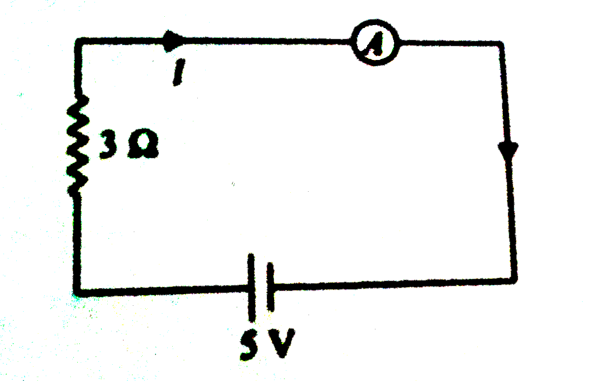
In the circuit shown in figure, the current is to measured. What is the value of the current if the ammeter shown (i) is a galvanometer with a resistance . (ii) is a galvanometer described in (i) but converted to an ammeter by a shunt resistance , (iii) is an ideal ammeter with zero resistance?
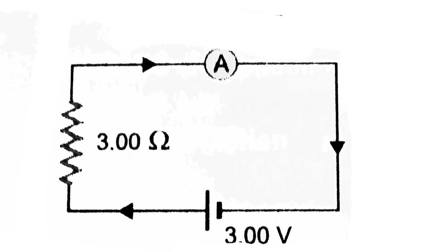
(a) Total resistance in the circuit is,
. Hence, .
(b) Resistance of the galvanometer converted to an ammeter is,
Total resistance in the circuit is,
. Hence, .
(c) For the ideal ammeter with zero resistance,
Topper's Solved these Questions
Similar Questions
Knowledge Check
A galvanometer of resistance 70Ω, is converted to an ammeter by a shunt resistance r3=0.03Ω. The value of its resistance will become
A0.025ΩB0.022ΩC0.035ΩD0.030Ω
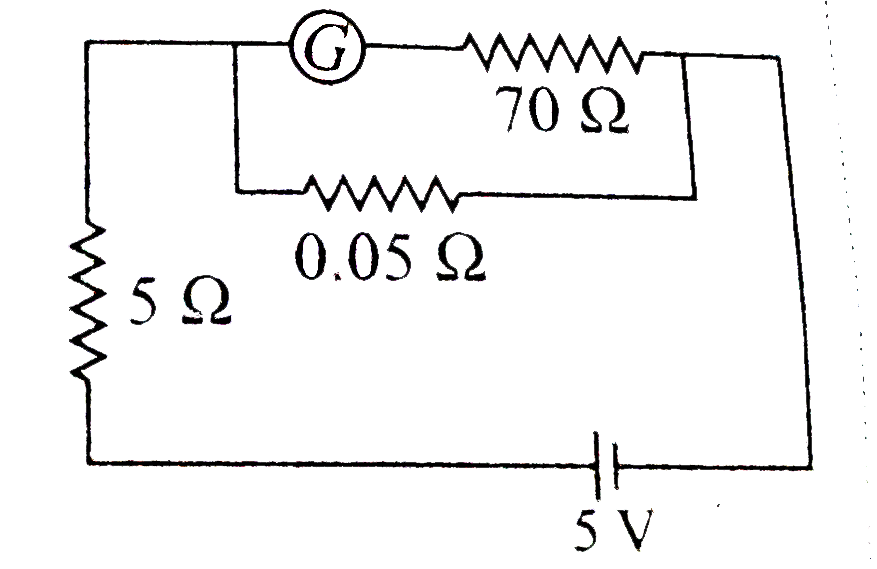
In the given circuit, a galvanometer with a resistance of 70Ω is converted to an ammeter 0.05Ω by a shunt resistance of 0.052, total current measured by this device
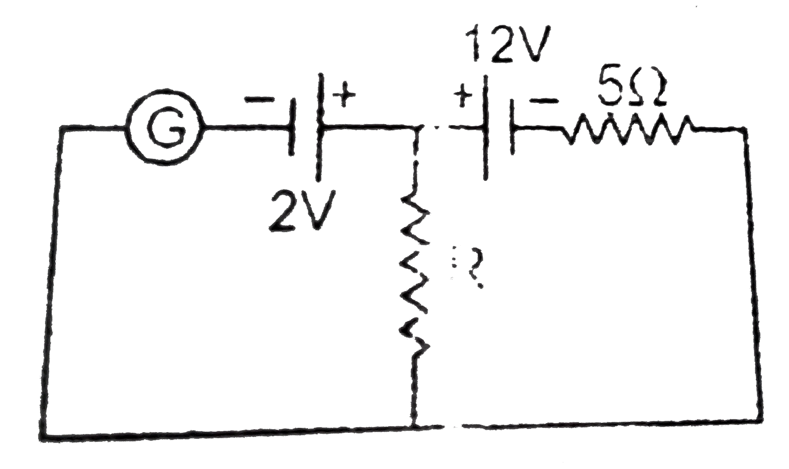
View SolutionIn the circuit shown, the galvanometer shows zero current. The value of resistance R is :
View SolutionIn the circuit shown, the galvanometer shows zero current. The value of resistance R is :

View SolutionIn the circuit shown in figure the reading of ammeter is the same with both switches open as with both closed. Then find the resistance R. (ammeter is ideal).
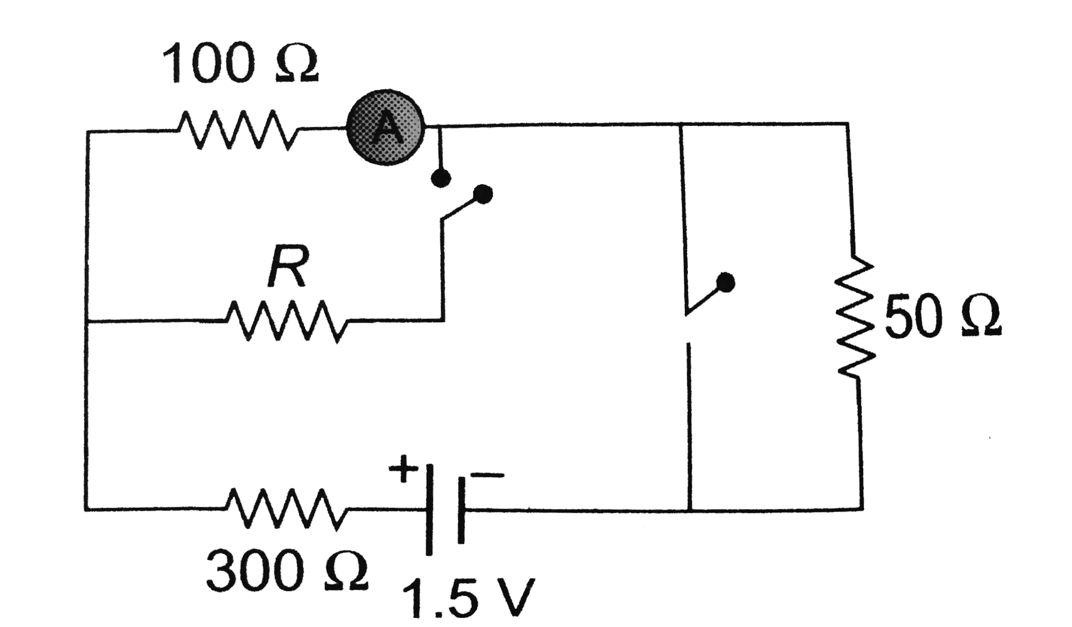
View SolutionIn the circuit shown in figure the reading of ammeter is the same with both switches open as with both closed. Then find the resistance R. (ammeter is ideal).

View SolutionIn the circuit shown in figure ammeter and voltmeter are ideal. If E=4V,R=9Ω and r=1Ω then readings of ammeter and voltmeter are
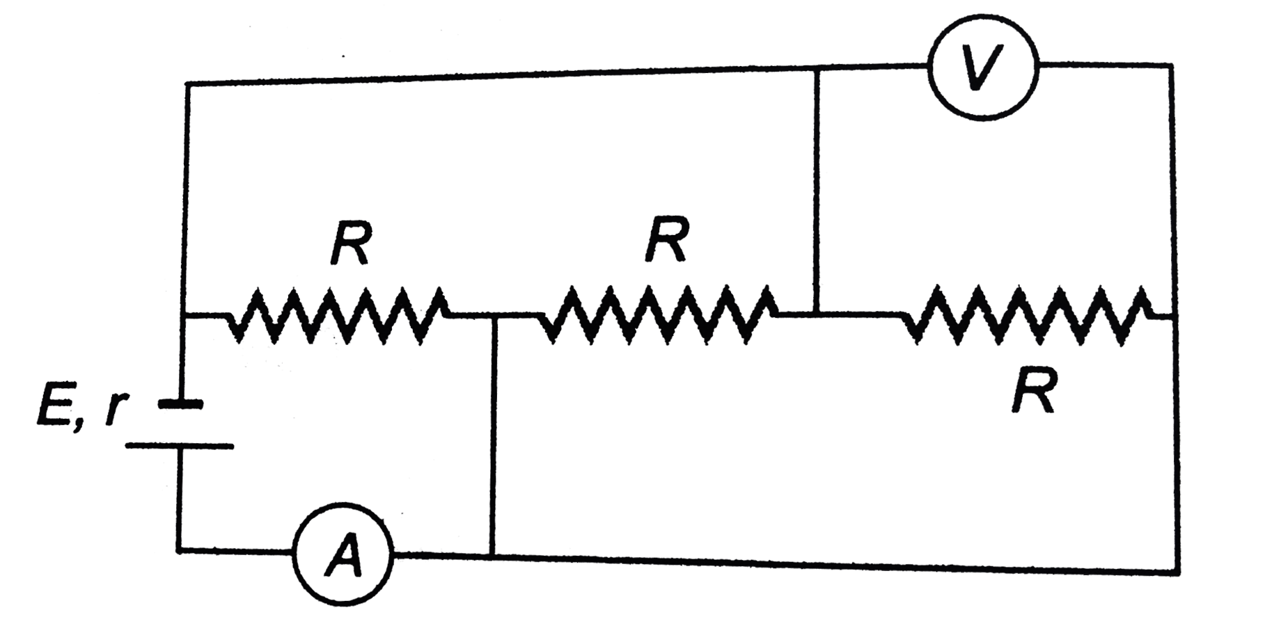
View SolutionIn the circuit shown in figure ammeter and voltmeter are ideal. If E=4V,R=9Ω and r=1Ω then readings of ammeter and voltmeter are

View Solution


