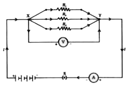
Draw the diagram of an electric circuit in which the resistors R1,R2andR3 are connected in parallel including an ammeter and a voltmeter and mark the direction of the current.Solution in Kannada
Topper's Solved these Questions
- ELECTRICITYBOOK - ZEN PUBLICATIONCHAPTER - ELECTRICITYEXERCISE - ZEN ADDITIONAL QUESTIONS SECTION (SHORT ANSWER TYPE 2 QUESTIONS)
24 Videos
- ELECTRICITYBOOK - ZEN PUBLICATIONCHAPTER - ELECTRICITYEXERCISE - ZEN ADDITIONAL QUESTIONS SECTION (LONG ANSWER QUESTIONS)
30 Videos
- ELECTRICITYBOOK - ZEN PUBLICATIONCHAPTER - ELECTRICITYEXERCISE - ZEN ADDITIONAL QUESTIONS SECTION (VERY SHORT ANSWER TYPE QUESTIONS)
42 Videos
- LIGHT - REFLECTION AND REFRACTIONBOOK - ZEN PUBLICATIONCHAPTER - LIGHT - REFLECTION AND REFRACTIONEXERCISE - ZEN ADDITIONAL QUESTIONS SECTION (LONG ANSWER [LA] QUESTIONS)
30 Videos
Similar Questions
Three 2Ω resistors, A, B and C, are connected as shown in figure. Each of them dissipates energy and can withstand a maximum power of 18 W without melting. Find the maximum current that can flow through the three resistors?

View SolutionState Ohm's law? How can it be verified experimentally? Does it hold good under all conditions? Comment.
View SolutionWhat is meant by saying that the electric potential at a point is Ivolt?
View SolutionDraw ray diagrams showing the image formation by a concave mirror when an object is placed.
(a) between pole and focus of the mirror
(b) between focus and centre of curvature of the mirror
(c ) at centre of curvature of the mirror
(d) a little beyond centre of curvature of the mirror
(e ) at infinity
View SolutionFind the currents going through the three resistors R_(v),R_(2)andR_(3) in the circuit of figure.

View SolutionFor three circuits, shown here the same two resistors R_(1) and R_(2) have been connected in parallel in all the circuits but the voltmeter and the ammeter have been connected in three different positions. The relation between the three voltmeter and ammeter readings would be :
View SolutionR_(1),R_(2)andR_(3) resistors are connected in parallel in a circuit with a battery voltmeters and ammeters. Draw the circuit for the given situation.
View SolutionDraw the circuit diagram showing the combination of resistors R1,R2 and R3 in parallel including ammeter and voltmeter and mark the direction of current.
View SolutionDraw the diagram of the electric circuit in which the resistors R_1, R_2 and R_3 are connected in series including ammeter and voltmeter and mark the direction of current .
View SolutionDraw the diagram of an electric circuit in which the resistors R1,R2 and R3 are connected in parallel including an ammeter and a voltmeter and mark the direction of the current.
View SolutionDraw the diagram of an electric circuit in which the resistors R_(1), R_(2) and R_(3) are connected in parallel aincluding an ammeter and a voltmeter and mark the direction of the current.
View SolutionDraw the diagram of an electric circuit in which the resistors R1,R2andR3 are connected in parallel including an ammeter and a voltmeter and mark the direction of the current.
View SolutionDraw the diagram of an electric circuit in which the resistors R1,R2andR3 are connected in parallel including an ammeter and a voltmeter and mark the direction of the current.
View SolutionDraw the diagram of an electric circuit in which the resistors R1,R2andR3 are connected in parallel including an ammeter and a voltmeter and mark the direction of the current.
View SolutionDraw the diagram of an electric circuit in which the resistors R1,R2andR3 are connected in parallel including an ammeter and a voltmeter and mark the direction of the current.
View SolutionDraw the diagram of an electric circuit in which the resistors R1,R2andR3 are connected in parallel including an ammeter and a voltmeter and mark the direction of the current.
View Solution

