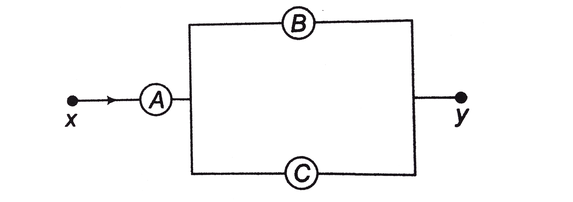
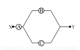
A, B and C are voltmeters of resistance R, 1.5R and 3R respectively as shown in the figure. When some potential difference is applied between X and Y, the voltmeter readings are VA,VBandVC respectively. Then

VA=VB≠VC
VA≠VB≠VC
VA=VB=VC
VA≠VB=VC
The correct Answer is:C
The current flowing in the different branches of circuit is indicated in the figure.
VA=IR
VB=2I3×32R=IR
VC=I3×3R=IR
Thus, VA=VB=VC

Topper's Solved these Questions
- CURRENT ELECTRICITY Book:MTG GUIDEChapter:CURRENT ELECTRICITY Exercise:CHECK YOUR NEET VITALS
Explore 16 Videos
- ATOMS AND NUCLEIBook:MTG GUIDEChapter:ATOMS AND NUCLEIExercise:AIPMT/NEET(MCQs)
Explore 40 Videos
- DUAL NATURE OF MATTER AND RADIATION Book:MTG GUIDEChapter:DUAL NATURE OF MATTER AND RADIATION Exercise:AIPMT/ NEET MCQs
Explore 30 Videos
Similar Questions
A,B and C are voltmeters of resistances R,1.5R and 3R respectively. When some potential difference is applied between x and y the voltmeter readings are VA,VBandVC, then

View SolutionA,B and C are voltmeters of resistances R,1.5R and 3R respectively. When some potential difference is applied between x and y the voltmeter readings are VA,V_BandV_C, then

View Solution
Knowledge Check
A,B and C are voltmeters of resistance R, 1.5 R and 3R respectively as shown in the figure. When some potential difference is applied between X and Y, the voltmeter reading are VA,VBandVC respectively.
AVA=AB≠VCBVA≠VB≠VCCVA=AB=VCDVA≠VB=VCA,B and C are voltmeters of resistances R,1.5R and 3R respectively. When some potential difference is applied between x and y the voltmeter readings are VA,V_BandV_C, then
 AVA=VB=VCBVA≠VB=VCCVA=VB≡VCDVA+VB=VC
Three voltmeters A, B and C having resistances R, 1.5 R and 3 R respectively are used in a circuit as shown. When a potential difference is applied between X and Y, the readings of the voltmeters are V1,V2andV3respectively. Then :
 AV1=V2=V3BV1<V2=V3CV1>V2>V3DV1>V2=V3
A,B and C are voltmeters of resistances R,1.5R and 3R respectively. When some potential difference is applied between x and y the voltmeter readings are VA,V_BandV_C, then

View SolutionA,B and C are voltmeters of resistances R,1.5R and 3R respectively. When some potential difference is applied between x and y the voltmeter readings are VA,V_BandV_C, then

View SolutionThree voltmeters A, B and C having resistances R, 1.5 R and 3 R respectively are used in a circuit as shown. When a potential difference is applied between X and Y, the readings of the voltmeters are V1,V2andV3respectively. Then :

View SolutionThree voltmeters A, B and C having resistances R, 1.5 R and 3 R respectively are used in a circuit as shown. When a potential difference is applied between X and Y, the readings of the voltmeters are V1,V2andV3respectively. Then :

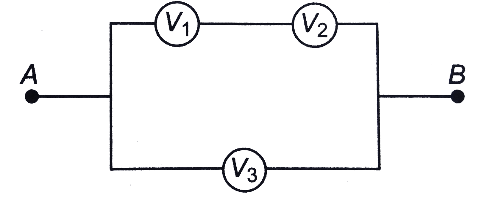
View SolutionThree voltmeters all having different resistance, are joined as shown. When some potential difference is applied acros A and B, their readings are V1,V2 and V3. Then

View Solution
