Consider a box with three terminals on top of it as shown in figure (a)
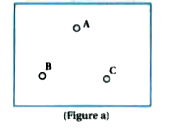
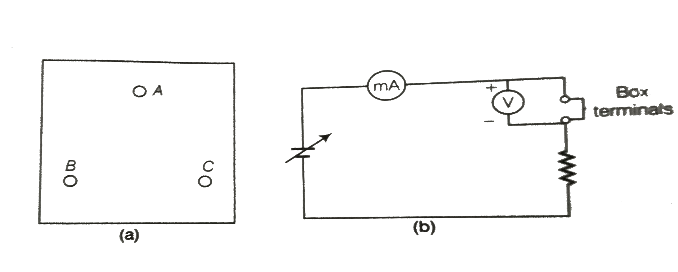
Three components namely, two germanium diodes and one resistor are connected across these three terminals in some arrangement. A student performs an experiment in which any two of these three terminals are connected in the circuit shown in figure (b).

The student obtains graphs of current-voltage characteristics for unknown combination of components between the two terminals connected in the ciruit.
The graphs are :
(i) When A is positive and B is negative

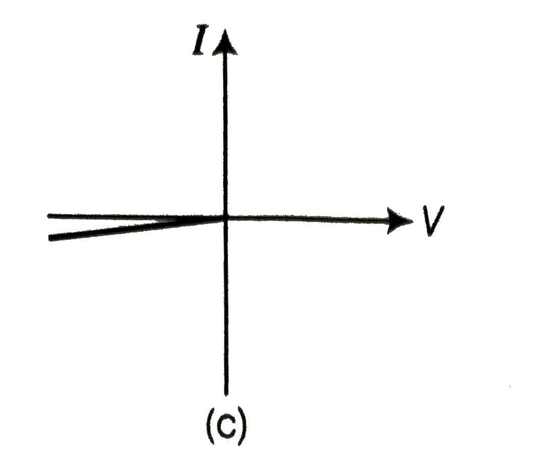
(ii) When A is negative and B is positive

(iii) When B is negative and C is positive

(iv) When B is positive and C is negative

(v) When A is positive and C is negative

(vi) When A is negative and C is positive

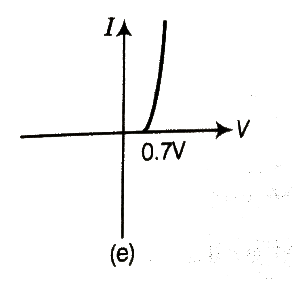
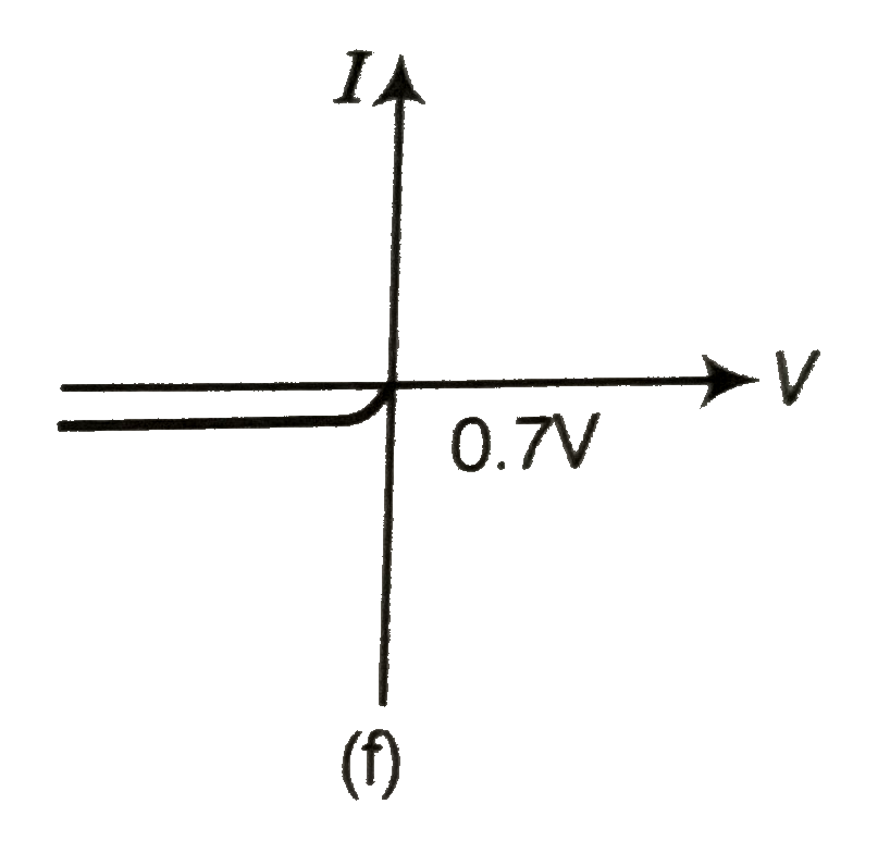
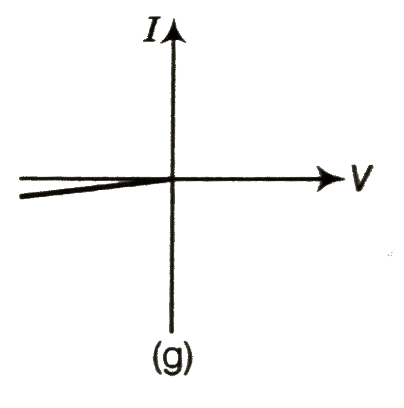
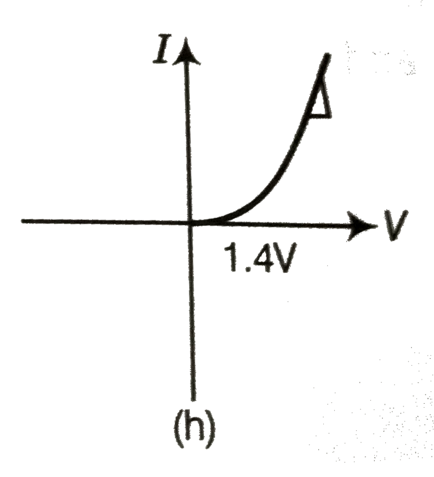
From these graphs of current - voltage characteristic shown in figure (c ) to (h), determine the arrangement of components between A, B and C.
For figure (c ) : This graph indicates reverse bias characteristics of a pn-junction diode, connected between terminals A and B as shown below.

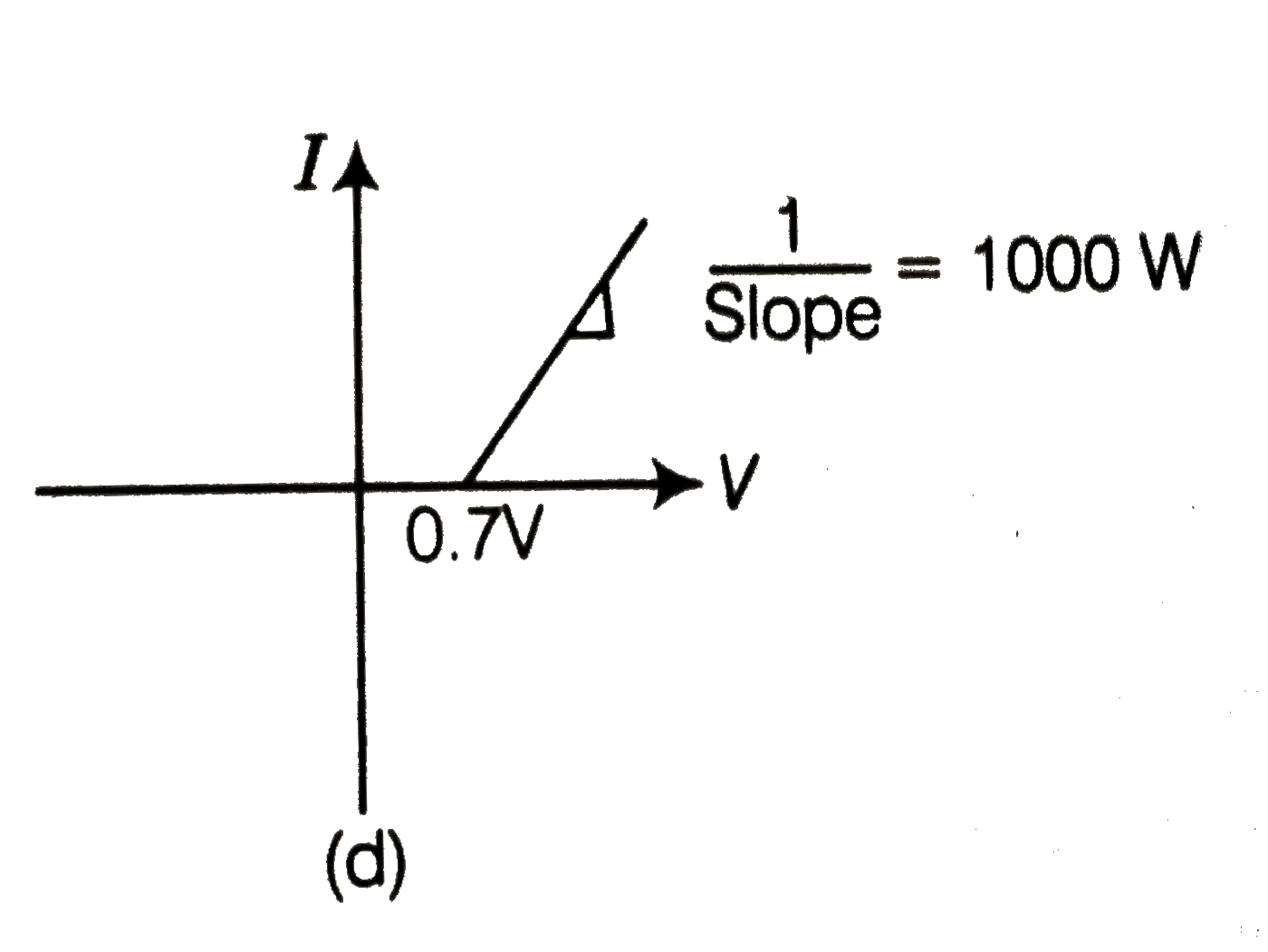
For figure (d) : This graph indicates forward bias characteristics of a pn-junction diode, connected between terminals A and B as shown below. (Where "knee voltage" or "cut in voltage" or "threshold voltage" is 0.7V and slope
=11000Ω−=IV=1Rf⇒Rf=1000Ω)

For figure (e ) : This graph indicates reverse bias characteristics of pn-junction diode, connected between points B and C, as shown below. (where knee voltage is 0.7V).

For figure (f) : This graph indicates reverse bias characteristics of pn-junction diode, connected between points B and C, as shown below.

For figure (g) : This graph indicates reverse bia characteristics of pn-junction diode, connected between points C and A, as shown below.

For figure (h) : This graph indicates forward bia characteristics of pn-junction diode, connected between points C and A, as shown below.

Final answer : Here internal connection made with three terminals A, B, C provided on the outer side of box will be as shown below.

Topper's Solved these Questions
- SEMICONDUCTOR ELECTRONICS : MATERIALS, DEVICES AND SIMPLE CIRCUITS BOOK - KUMAR PRAKASHANCHAPTER - SEMICONDUCTOR ELECTRONICS : MATERIALS, DEVICES AND SIMPLE CIRCUITS EXERCISE - Section-D : Multiple Choice Questions (MCQs) (MCQs From .DARPAN. Based On Textbook)
116 Videos
- SEMICONDUCTOR ELECTRONICS : MATERIALS, DEVICES AND SIMPLE CIRCUITS BOOK - KUMAR PRAKASHANCHAPTER - SEMICONDUCTOR ELECTRONICS : MATERIALS, DEVICES AND SIMPLE CIRCUITS EXERCISE - Section-D : Multiple Choice Questions (MCQs) (MCQs asked in Competitive Exams)
129 Videos
- SEMICONDUCTOR ELECTRONICS : MATERIALS, DEVICES AND SIMPLE CIRCUITS BOOK - KUMAR PRAKASHANCHAPTER - SEMICONDUCTOR ELECTRONICS : MATERIALS, DEVICES AND SIMPLE CIRCUITS EXERCISE - Section-C: NCERT Exemplar Solution (Short Answer Type Questions)
8 Videos
- SAMPLE QUESTION PAPER BOOK - KUMAR PRAKASHANCHAPTER - SAMPLE QUESTION PAPER EXERCISE - PART-B SECTION-C
5 Videos
- WAVE OPTICSBOOK - KUMAR PRAKASHANCHAPTER - WAVE OPTICSEXERCISE - SECTION-D (MULTIPLCE CHOICE QUESTIONS (MCQS)) (MCQS FROM DARPAN BASED ON TEXTBOOK)
239 Videos
Similar Questions
Consider a box with three terminals on top of it as shown in figure.
Three components namely, two germanium diodes and one resistor are connected across these three terminals in some arrangement
A student performs an experiment in which any two of these three terminals are connected in the circuit shown in figure.
The student obtains graphs of current-voltage characteristics for unknown combination of components between the two terminals connected in the circuit. The graphs are
(i) When A is positive and B is negative
(ii) When A is negative and B is positive
(iii) When B is negative and C is positve
(iv) When B is positive and C is neagtive
(v) When A is positive and C is negative
(vi) When A is negative and C is positive
From these graphs of current − voltage characteristic shown in fig. (c) to (h) determine the arrangement of components between A, B and C.
View SolutionConsider a box with three terminals on top of it as shown in figure.

Three components namely, two germanium diodes and one resistor are connected across these three terminals in some arrangement
A student performs an experiment in which any two of these three terminals are connected in the circuit shown in figure.
The student obtains graphs of current-voltage characteristics for unknown combination of components between the two terminals connected in the circuit. The graphs are
(i) When A is positive and B is negative

(ii) When A is negative and B is positive

(iii) When B is negative and C is positve

(iv) When B is positive and C is neagtive

(v) When A is positive and C is negative

(vi) When A is negative and C is positive

From these graphs of current − voltage characteristic shown in fig. (c) to (h) determine the arrangement of components between A, B and C.
View Solution
Knowledge Check
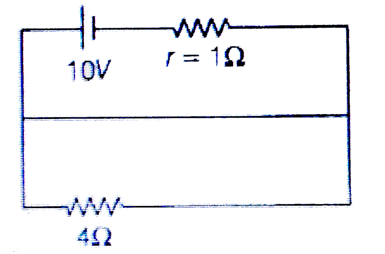
Potential different across the terminals of the battery shown in figure is
 A8 VB10 VC6 VDzero
Consider a box with three terminals on top of it as shown in figure.

Three components namely, two germanium diodes and one resistor are connected across these three terminals in some arrangement
A student performs an experiment in which any two of these three terminals are connected in the circuit shown in figure.
The student obtains graphs of current-voltage characteristics for unknown combination of components between the two terminals connected in the circuit. The graphs are
(i) When A is positive and B is negative

(ii) When A is negative and B is positive

(iii) When B is negative and C is positve

(iv) When B is positive and C is neagtive

(v) When A is positive and C is negative

(vi) When A is negative and C is positive

From these graphs of current − voltage characteristic shown in fig. (c) to (h) determine the arrangement of components between A, B and C.
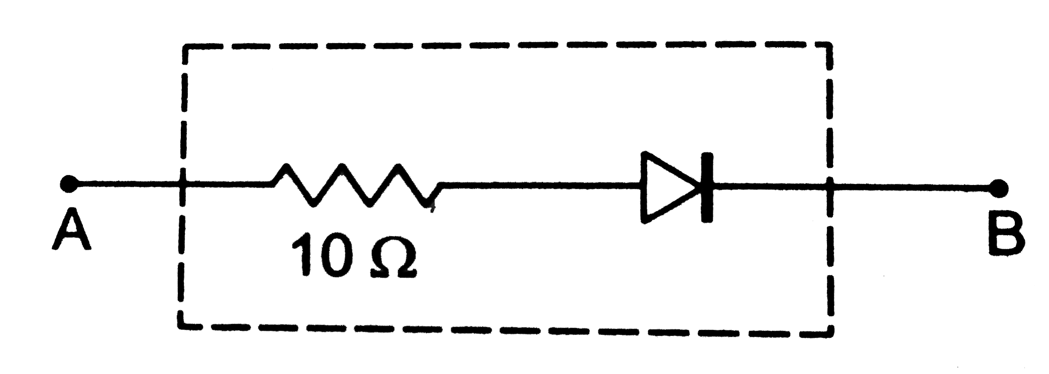
View SolutionDraw the current-voltage characteristics for the device shown in figure between the terminal A and B.

View SolutionPotential different across the terminals of the battery shown in figure is

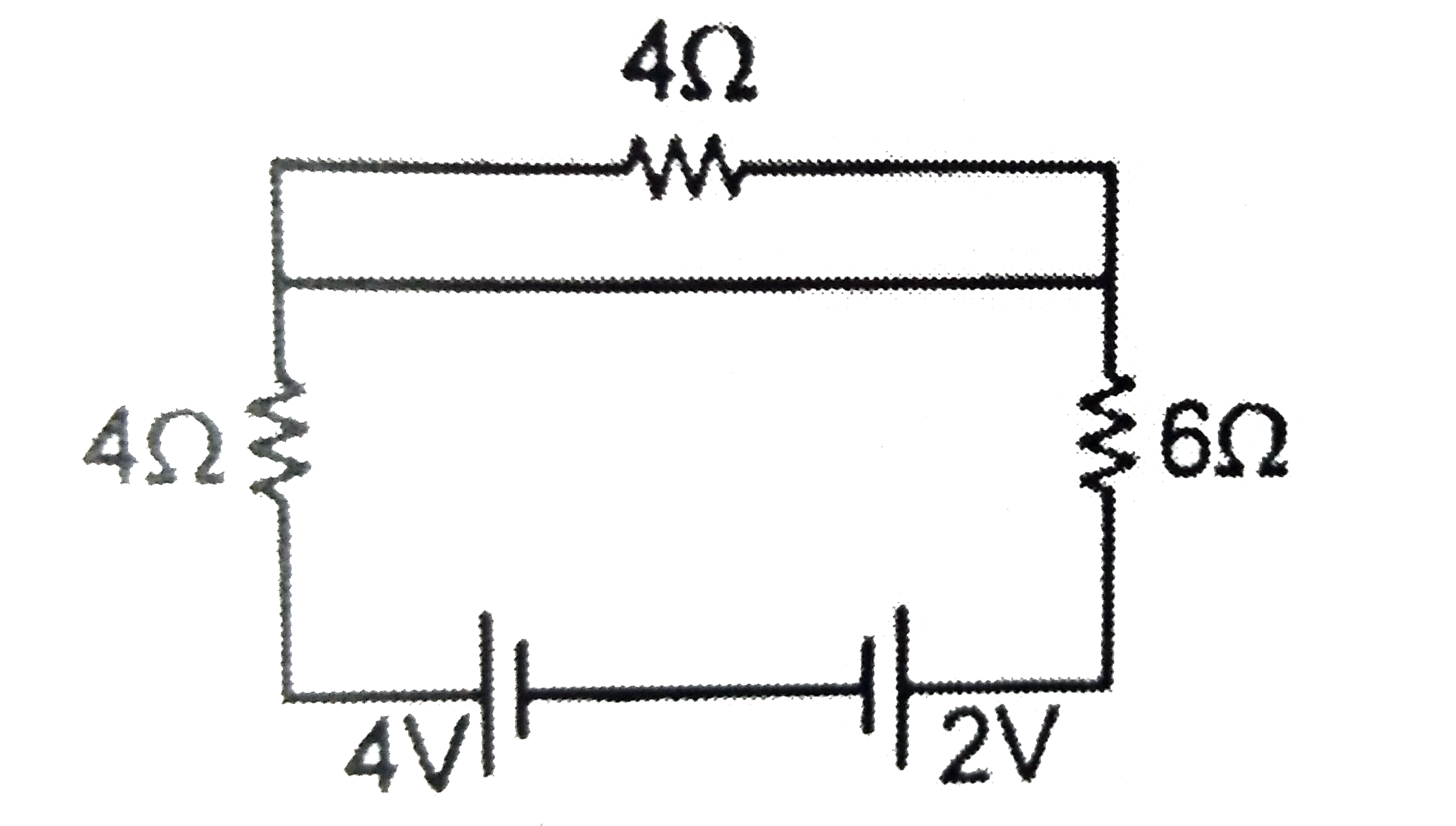
View SolutionFind the currents through the three resistors shown in figure
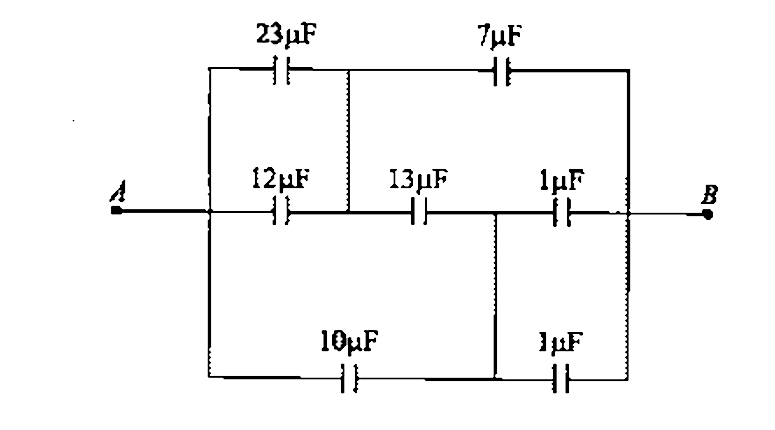
View SolutionFind the equivalent capacitance across terminals A and B in the circuit shown in figure.
View SolutionFind the currents through the three resistors shown in Figure
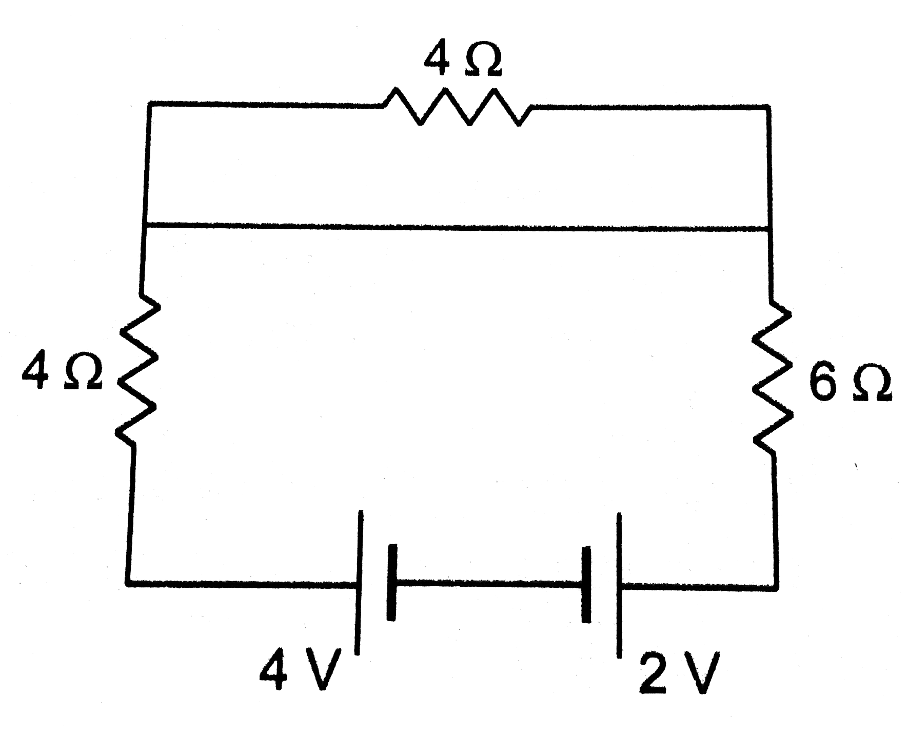
View SolutionFind the currents through the three resistors shown in Figure

View Solution
