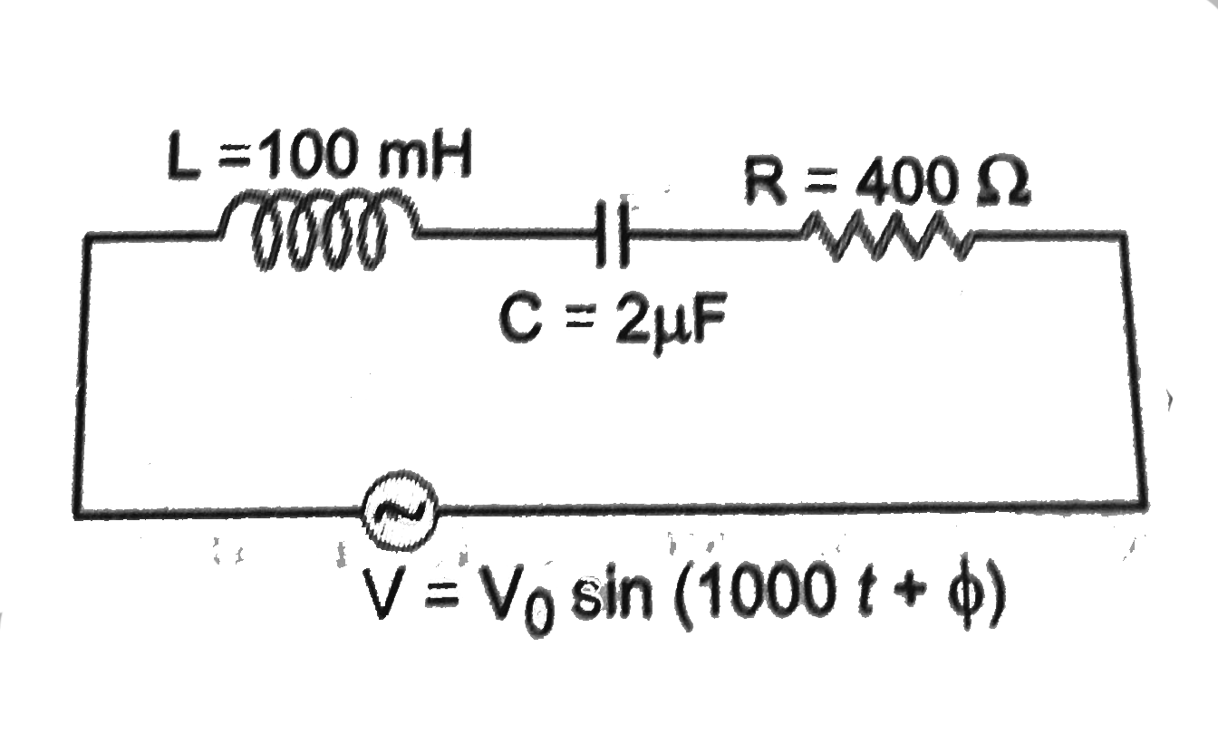
Find the value of phase lag/lead between the current and voltage in the given CLR circuit, fig. Without making any other change, find the value of additional capacitor, such that when joined switably to C=2μF, would make the power factor of this circuit unity.

Step by step video & image solution for Find the value of phase lag/lead between the current and voltage in the given CLR circuit, fig. Without making any other change, find the value of additional capacitor, such that when joined switably to C = 2 mu F, would make the power factor of this circuit unity. by Physics experts to help you in doubts & scoring excellent marks in Class 12 exams.
Updated on:21/07/2023Similar Questions
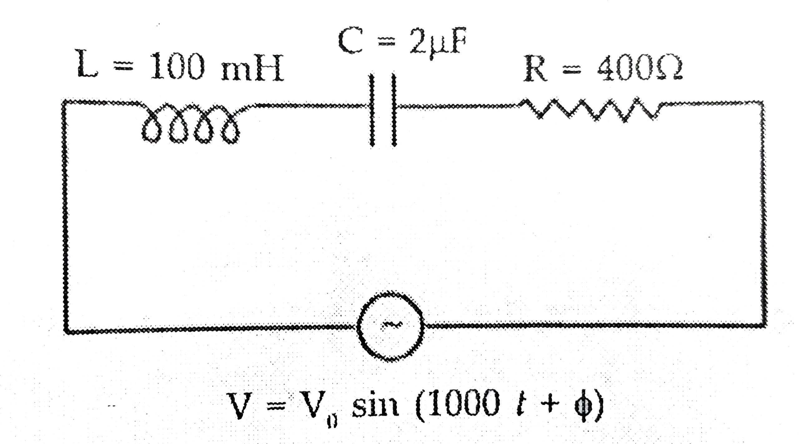
(i) Find the value of the phase difference between the current and the voltage in the series LCR circuit shown below. Which one leads in phase : current or voltage ?

(ii) What making any other change, find the value of the additional capacitor C, to be connected in parallel with the capacitor C, in order to make the power factor of the circuit unity.
View SolutionA capacitor (C) and a resistor (R) are connected in series with an a.c, source of voltage of frequency 50 Hz. The potential difference across C and R are respectively 120 V and 90 V. The current in the circuit is 3A. Calculate () impedance of the circuit, (i) value of the inductance which when connected in series with Cand R will make the power fador of the circuit unity.
View Solution
Knowledge Check
In an electrical circuit R,L,C and an AC voltage source are all connected in series. When L is removed from the circuit, the phase difference between the voltage and the current in the circuit is π/3. If instead, C is removed from the circuit, difference the phase difference is again π/3. The power factor of the circuit is
A12B1√2C1D√32

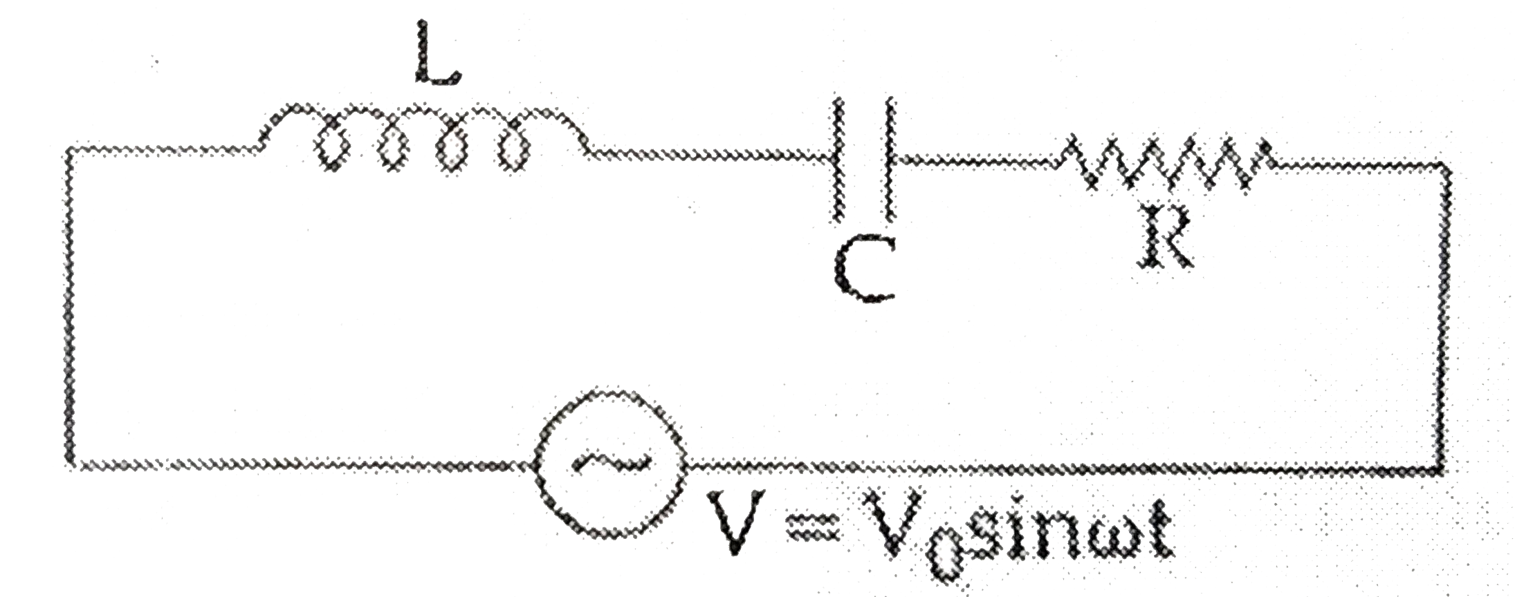
The current in the LCR circuit shown in the figure is observed to lead the voltage in phase. Without making any other change in the circuit, a capacitor, of capacitance C0 is (appropriately) joined to the capacitor C. This results in making the current, in the joined to the capacitor C. This results in making the current, in the modified' circuit, flow in phase with the applied voltage.
Draw a diagram of the modified circuit and obtain an expression of C0 in terms of Ω, L and C.
View SolutionIn an electrical circuit R,L,C and an AC voltage source are all connected in series. When L is removed from the circuit, the phase difference between the voltage and the current in the circuit is π/3. If instead, C is removed from the circuit, difference the phase difference is again π/3. The power factor of the circuit is
View SolutionIn the given circuit , the potential difference between A and B is 18 V and charge on 2 μF capacitor is 24 μ C . The value of C is

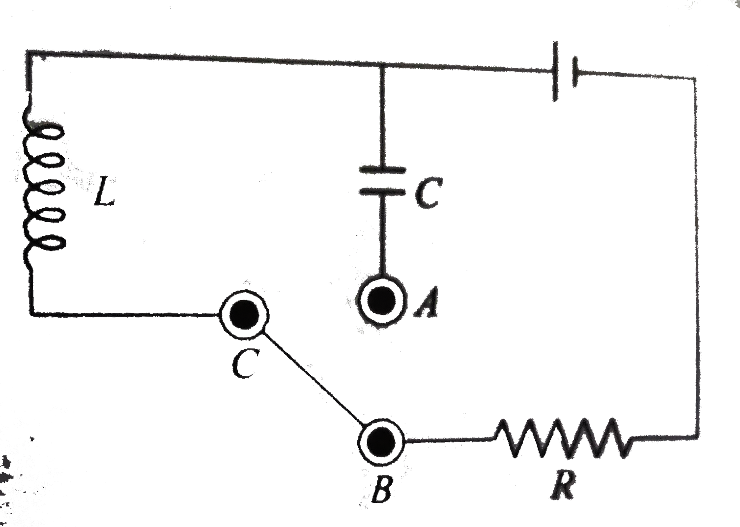
View SolutionIn the circuit shows in Fig the capacitor is initially uncharged and the two - way switch is connected in the position BC. Find the current through the resistence R as a function of time t. After time t=4 ms, the switch is connected in the position AC. Find the frequency of oscillation of the capacitor of the circuit in the position, and the maximum charge on the capacitor C. At what time will the energy stored in the capacitor be one-half of the total energy stored in the circuit? It is given L=2×10⁻⁴H,C=5mF,R=In210Ω and emf of the battery =1V.

View SolutionIn the given circuit, power factor between A and B is 0.5 and over all power factor of the circuit is 1.
Find the value of Rand L
View Solution(a) Deriver and expression for the average power consumed in a series LCR circuit connected to a.c., source in which the phase different between the voltage and the current in the circuit is ϕ.
(b) Define the quality factor in an a.c. circuit. Why should the quality factor have high value in receiving circuits ? Name the factors on which it depends.
View SolutionIn an electrical circuit R,L, C and a.c voltage source are all connected in series. When L is removed from the circuit , the phase difference between the voltage and current in the circuit is π/6. If instead ,C is removed from the circuit , the phase difference is again π/6 . The power factor of the circuit is
View Solution
