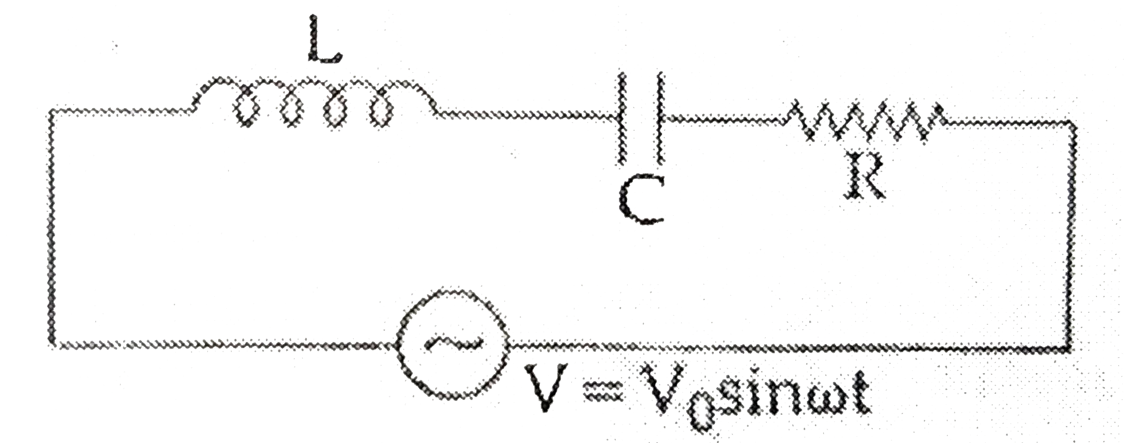
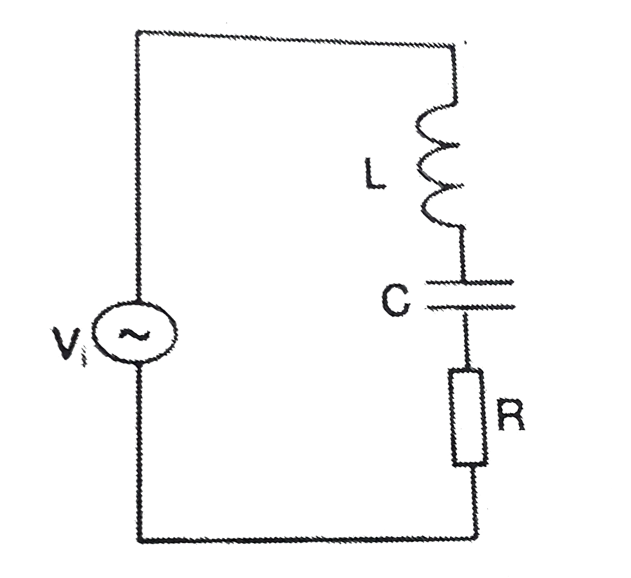
The current in the LCR circuit shown in the figure is observed to lead the voltage in phase. Without making any other change in the circuit, a capacitor, of capacitance C0 is (appropriately) joined to the capacitor C. This results in making the current, in the joined to the capacitor C. This results in making the current, in the modified' circuit, flow in phase with the applied voltage.
Draw a diagram of the modified circuit and obtain an expression of C0 in terms of Ω, L and C.
Step by step video & image solution for The current in the LCR circuit shown in the figure is observed to lead the voltage in phase. Without making any other change in the circuit, a capacitor, of capacitance C_0 is (appropriately) joined to the capacitor C. This results in making the current, in the joined to the capacitor C. This results in making the current, in the modified' circuit, flow in phase with the applied voltage. Draw a diagram of the modified circuit and obtain an expression of C_0 in terms of Omega, L and C. by Physics experts to help you in doubts & scoring excellent marks in Class 12 exams.
Updated on:21/07/2023Similar Questions
Knowledge Check
In series LCR circuit, the phase angle between supply voltage and current is
Atanϕ=XL−XCRBtanϕ=RXL−XCCtanϕ=RXL+XCDtanϕ=XL+XCR
Show that the current leads the voltage in phase by π/2 in an a.c. circuit containing an ideal capacitor.
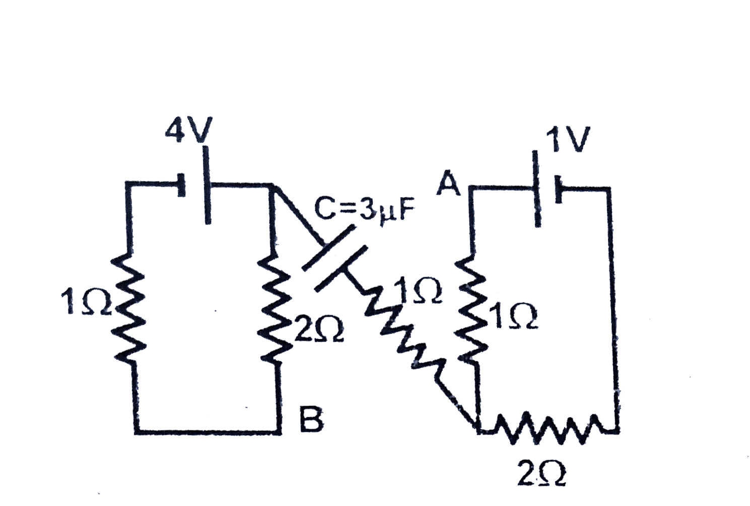
View SolutionIn the circuit shown in the adjacent figure, the batteries are ideal. The charge on the capacitor C is
View SolutionA capacitor of capacitance C has potential difference E2 and another capacitor of capacitance 2C is uncharged. They are joined to form a closed circuit as shown in the figure.
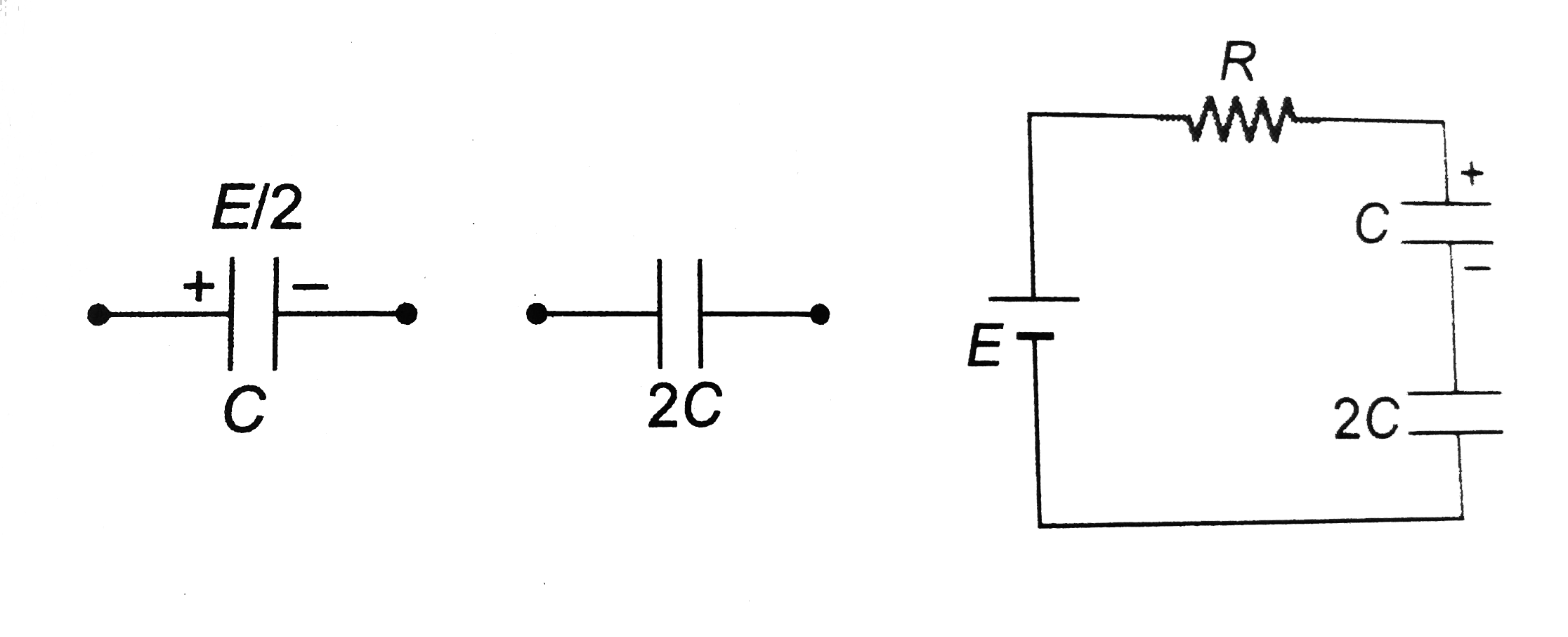
a. Find the current in the circuit at t =0.
b. Find the charge on C as a function of time.
View Solution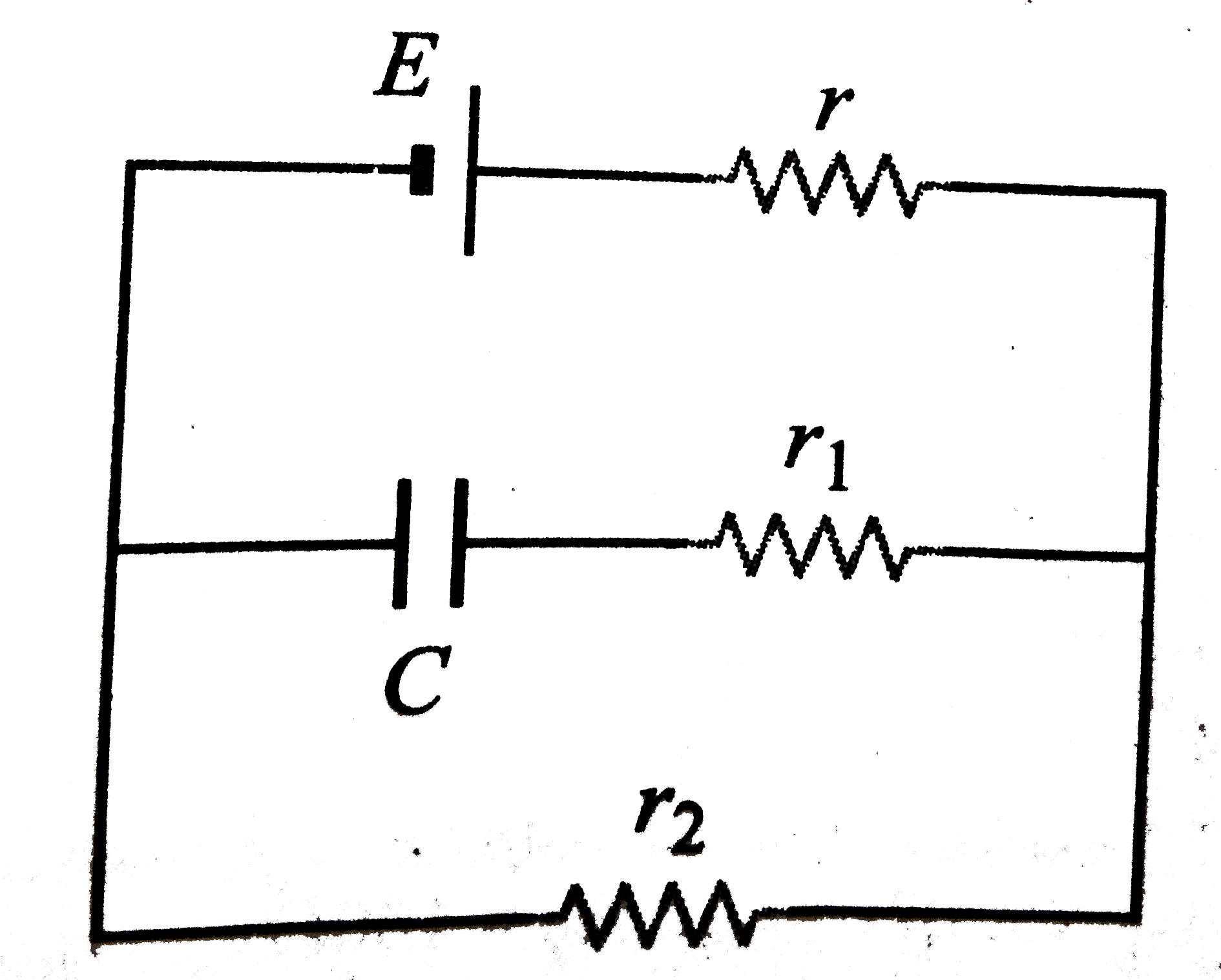
In the given circuit diagram when the current reaches steady state in the circuit, the charge on the capacitor of capacitance C will be:-
View SolutionAn inductor coil joined to a 6V battery draws a steady current of 12A. This coil is connected to a capacitor and an AC source of rms voltage 6V in series. If the current in the circuit is in phase with the emf, find the rms current.
View SolutionIn the following circuit the current is in phase with the applied voltage. Therefore, the current in the circuit and the frequency of the source voltage respectively, are
View SolutionFor the circuit shown in figure below, at t = 0, switch is closed, the initial current through resistor and final charge on capacitor are

View Solution

