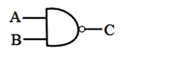
Logic gate for input A and B is given in figure
_2019_CBT7_E01_022_Q01.png)
Which table is correct for given gates system.
∣∣ ∣ ∣ ∣ ∣ ∣∣ABY000101010111∣∣ ∣ ∣ ∣ ∣ ∣∣
∣∣ ∣ ∣ ∣ ∣ ∣∣ABY000101011110∣∣ ∣ ∣ ∣ ∣ ∣∣
∣∣ ∣ ∣ ∣ ∣ ∣∣ABY001100011110∣∣ ∣ ∣ ∣ ∣ ∣∣
∣∣ ∣ ∣ ∣ ∣ ∣∣ABY001101010110∣∣ ∣ ∣ ∣ ∣ ∣∣
The correct Answer is:A
Step by step video & image solution for Logic gate for input A and B is given in figure Which table is correct for given gates system. by Physics experts to help you in doubts & scoring excellent marks in Class 12 exams.
Updated on:21/07/2023Topper's Solved these Questions
Similar Questions
For given logic gate truth table is

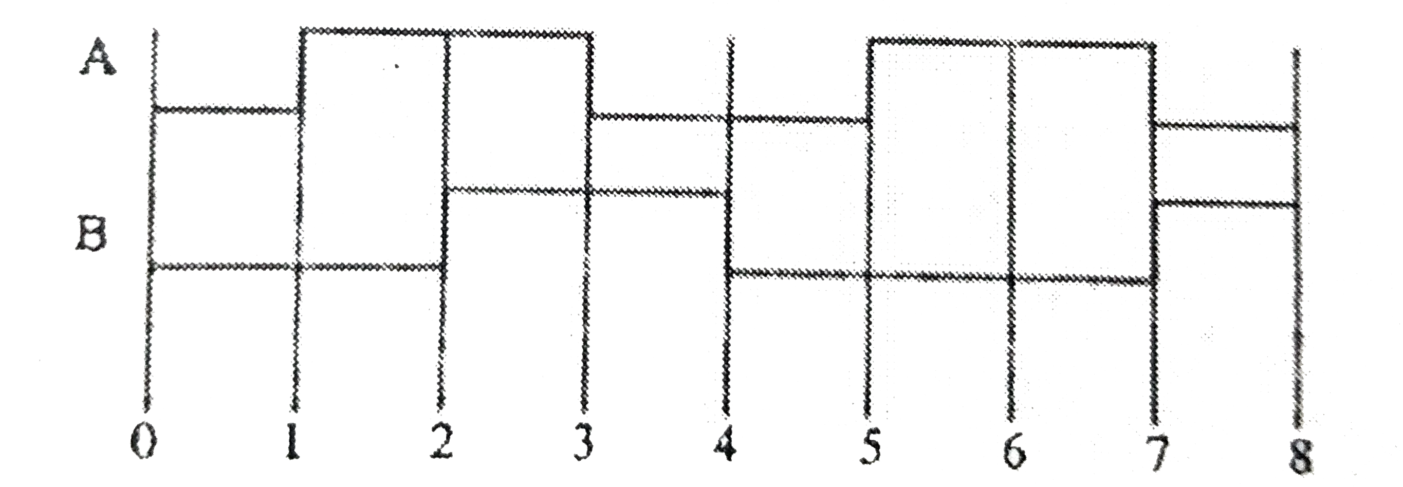
View Solution(i) Sketch the output waveform from an AND gate for the inputs A and B shown in the figure.

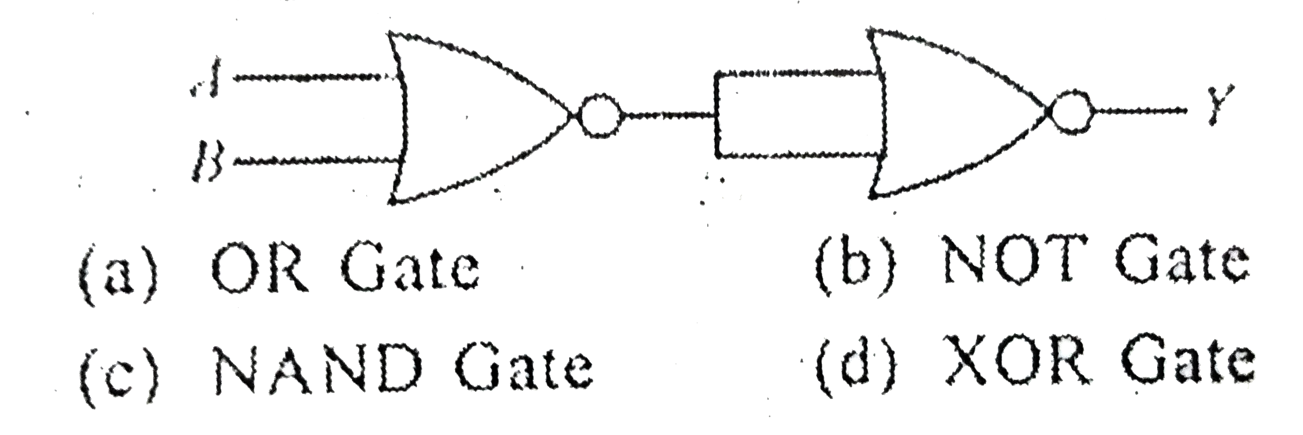
(ii) If the output of the above AND gate is fed to a NOT gate, name the gate of the combination so formed.
View SolutionLogic gate realised from pn Junctions shown in figure is
View SolutionThe output of the given logic gate is

View SolutionIdentify the gates P and Q shown in the figure. Write the truth table for the combination of the gates shown.

Name the equivalent gate representing this circuit and write its logic symbol.
View SolutionThe output of the given logica gate is

View SolutionTo which logic gate does the truth table given in the figure correspond?
View SolutionWhat is the out put of the given logic gate

View SolutionThe logic gate represented in following figure is

View SolutionThe following truth table corresponds to the logical gate

View Solution