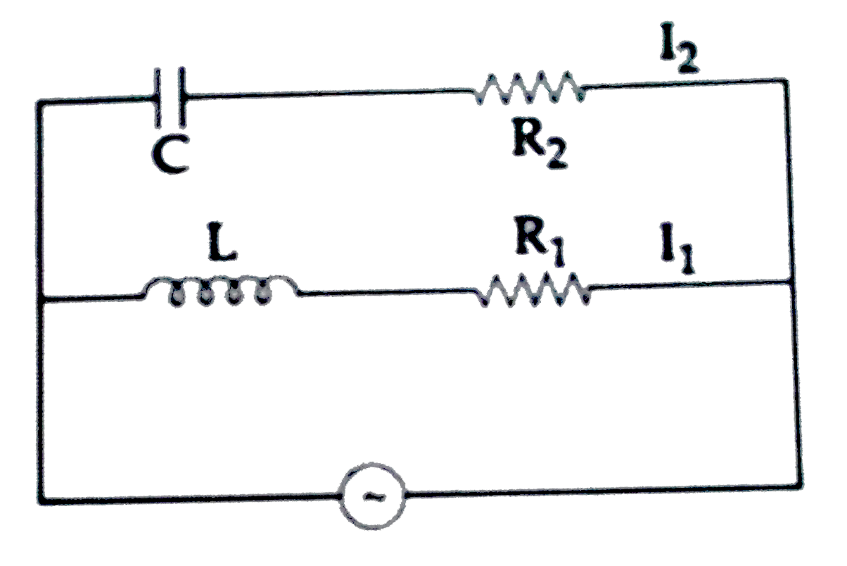
In the value circuit, C=√32μF,R2=20Ω,L=√310H, and R1=10Ω .Current in L−R1 path is I1 and in C−R2 path it is I2. The voltage of A.C source is given by, V=200√2sin(100t) volts. The phase difference between I2 and I1 is :
60∘
150∘
90∘
0∘
The correct Answer is:A
NA
Similar Questions
In the circuit shown in figure :
R=10Ω,L=√310H,R2=20Ω and C=√32mF. Current in L−R1 circuit is I1 in C−R1 circuit is I2 and the main current is I
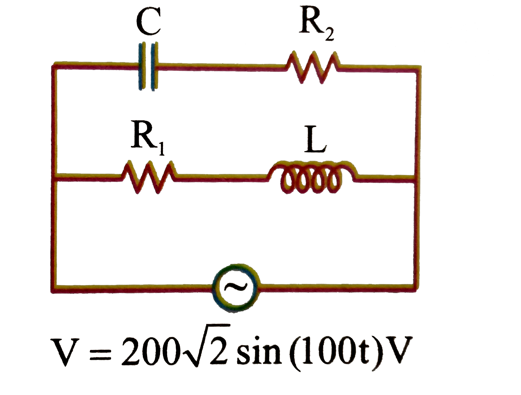
Phase difference between I1 and I2 is
View SolutionIn the circuit shown in figure :
R=10Ω,L=√310H,R2=20Ω and C=√32mF. Current in L−R1 circuit is I1 in C−R1 circuit is I2 and the main current is I

Phase difference between I1 and I2 is
View SolutionA 200Ω resistor and 1H inductor are joined in series with an ac source of emf 10√2sin(200t)V. Calculate the phases difference between emf and current.
View SolutionIn the circuit shown in figure :
R=10Ω,L=√310H,R2=20Ω and C=√32mF. Current in L−R1 circuit is I1 in C−R1 circuit is I2 and the main current is I
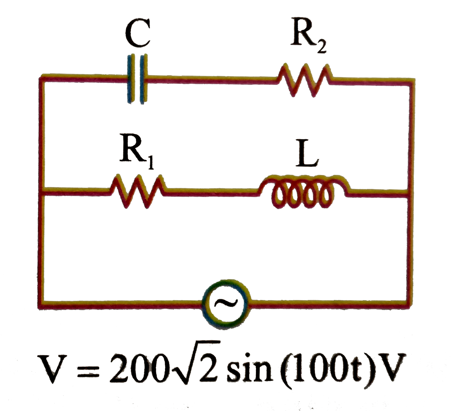
At some instant current in L−R1 circuit is 10A. At the same instant current in C−R2 branch will be
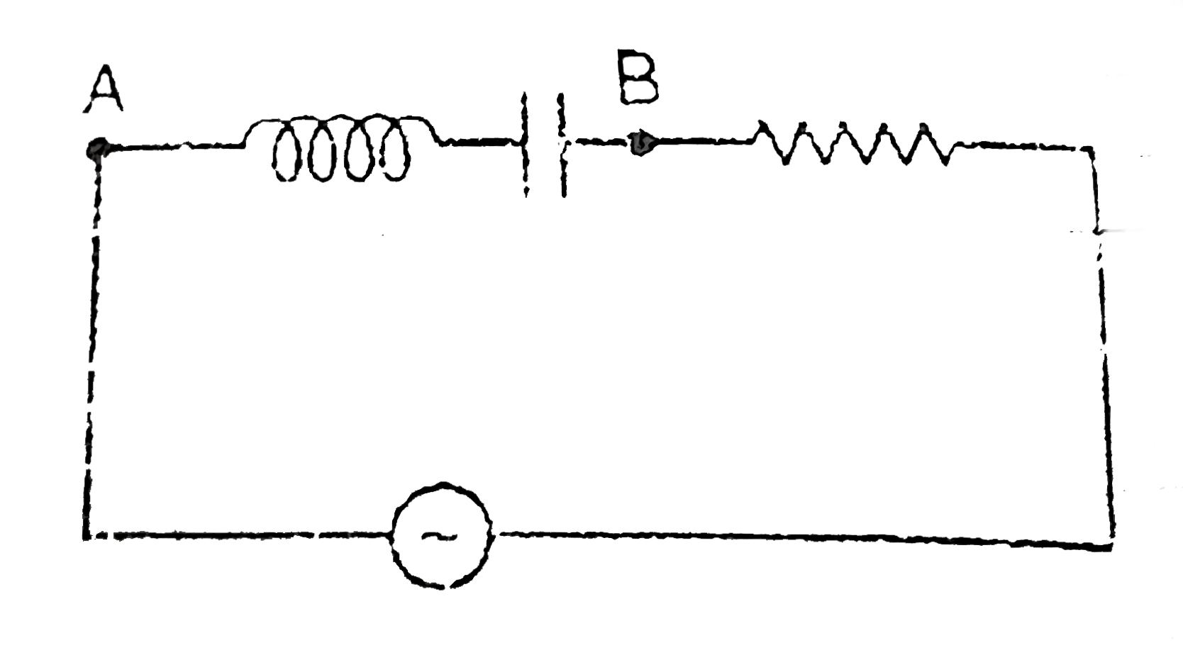
View SolutionAn inductor (L=1100πH), a capacitor (C=1500πF) and a resistance (3Ω) is connected in series with an AC voltage source as shown in the figure. The voltage of the AC source is given as V=10cos(100πt) volt. What will be the potential difference between A and B ?
View SolutionIn the following circuit ,E1=4V,R1=2Ω,
E2=6V,R2=2Ω,andR3=4Ω. Find the currents i1andi2
View SolutionFor a series RLC circuit R=XL=2XC. The impedence of the current and phase different (between) V and i will be
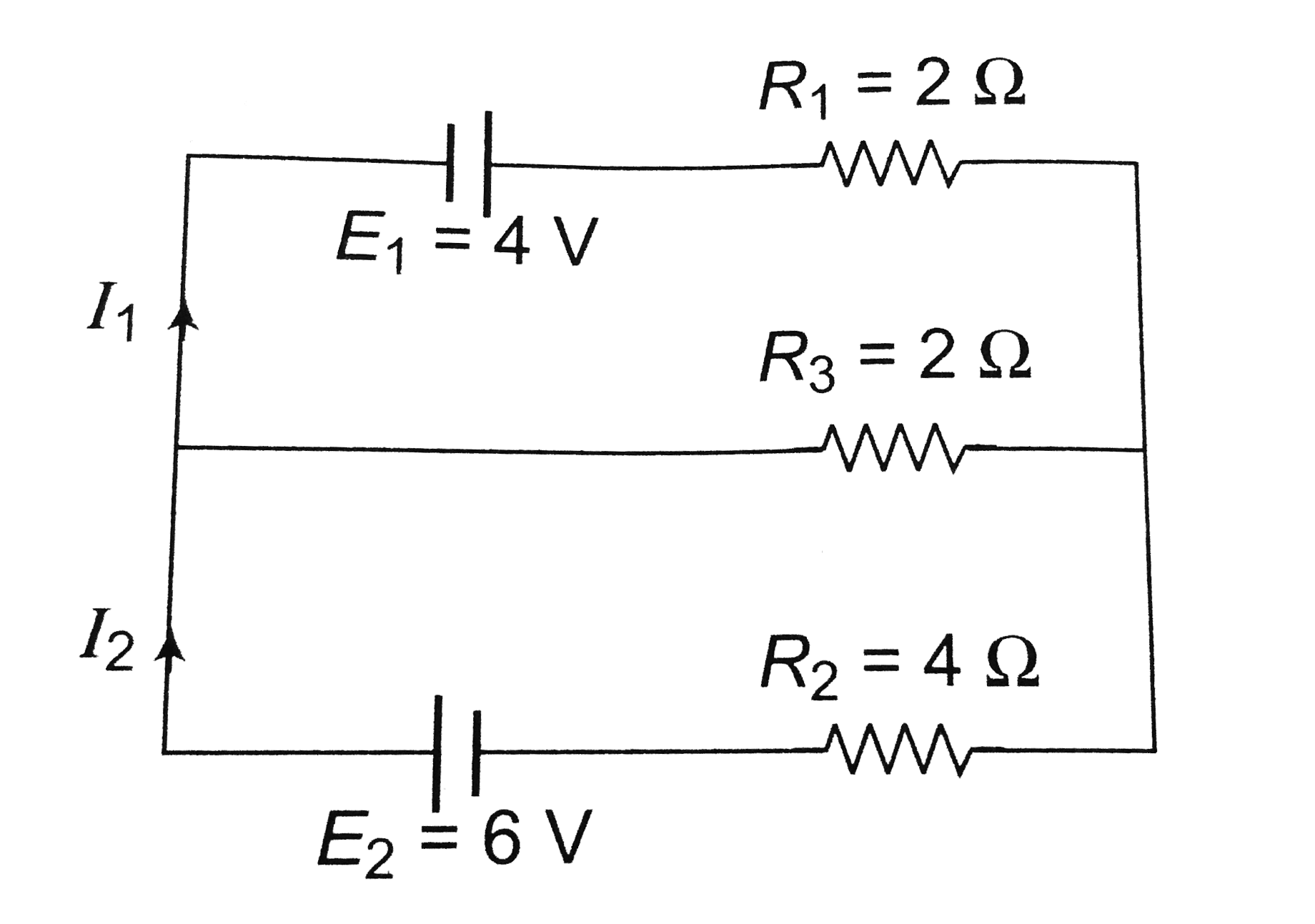
View SolutionIn the circuit shown below E1=4.0V,R1=2Ω,E2=6.0V,R2=4Ω and R3=2Ω. The current I1 is
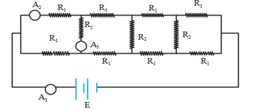
View SolutionIn the given circuit, R1 = 10Ω R2=6Ω and E = 10V, then correct statement is
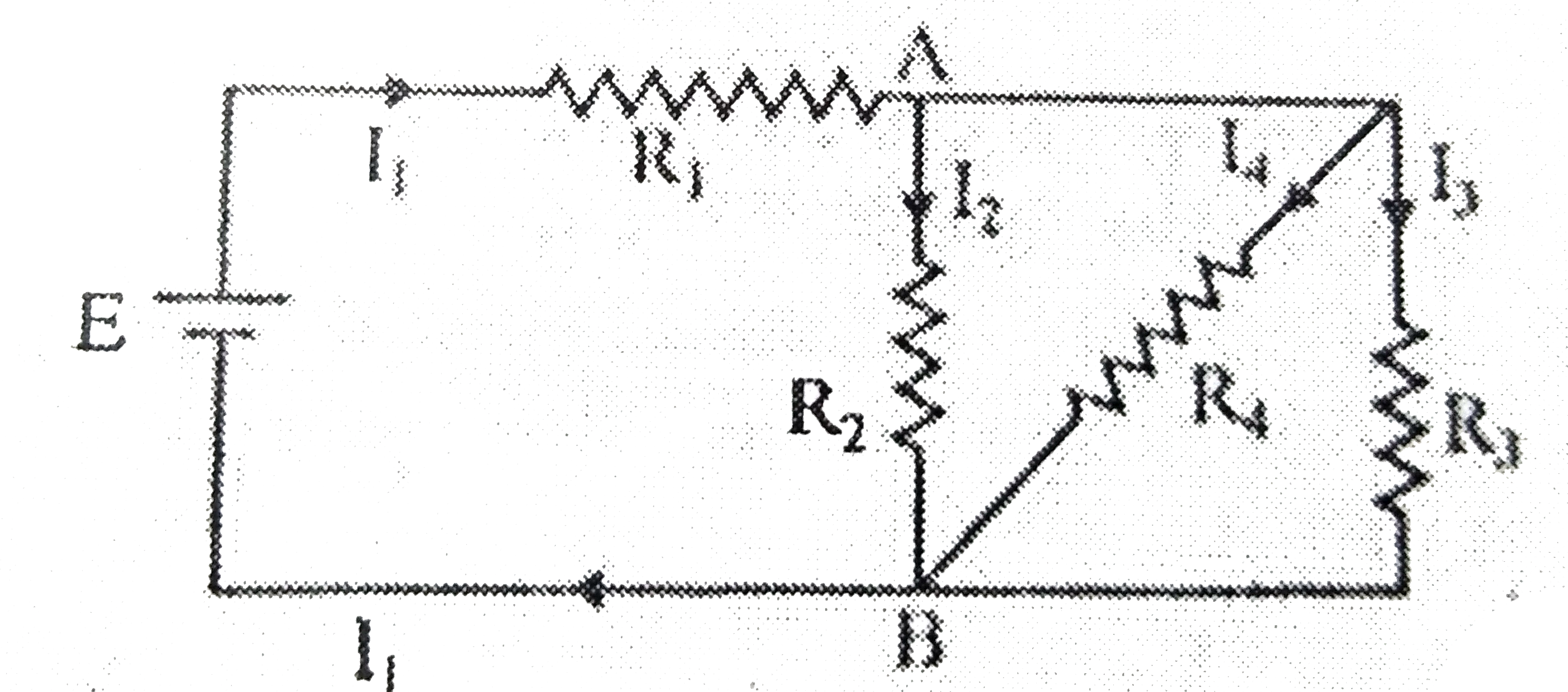
View SolutionIn the circuit shown, R1=2Ω,R2=R3=10Ω,R4=20ΩandE=6V. Work out the equivalent resistance of the circuit and the current in each resistor.
View Solution
