Which of the following wiring diagrams could be used to experimentally determine R using ohm.s law? Assume an ideal voltmeter and an ideal ammeter.
A
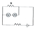
B
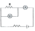
C
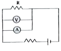
D
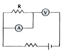
Text Solution
The correct Answer is:B
|
Topper's Solved these Questions
- CURRENT ELECTRICITYBOOK - AAKASH SERIESCHAPTER - CURRENT ELECTRICITYEXERCISE - PRACTICE SHEET (EXERCISE - I LEVEL-II (ADVANCED) (More than One correct answer Type Questions))
1 Videos
- CURRENT ELECTRICITYBOOK - AAKASH SERIESCHAPTER - CURRENT ELECTRICITYEXERCISE - PRACTICE SHEET (EXERCISE - I LEVEL-II (ADVANCED) (Integer Type Questions))
2 Videos
- CURRENT ELECTRICITYBOOK - AAKASH SERIESCHAPTER - CURRENT ELECTRICITYEXERCISE - PRACTICE SHEET (EXERCISE - I LEVEL-I (MAIN) (Straight Objective Type Questions))
4 Videos
- CURRENT ELECTRICITYBOOK - AAKASH SERIESCHAPTER - CURRENT ELECTRICITYEXERCISE - PROBLEMS (LEVEL-II)
26 Videos
- DUAL NATURE OF RADIATION AND MATTERBOOK - AAKASH SERIESCHAPTER - DUAL NATURE OF RADIATION AND MATTEREXERCISE - PRACTICE EXERCISEX
44 Videos
Similar Questions
Knowledge Check
Express which of the following set ups can be used to verify
ohm's law?A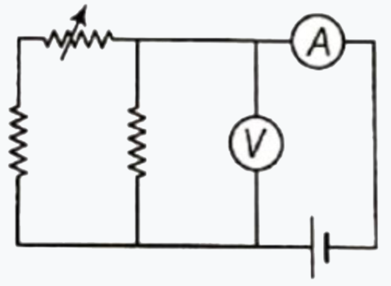 B
B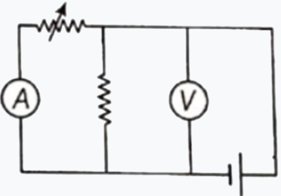 C
C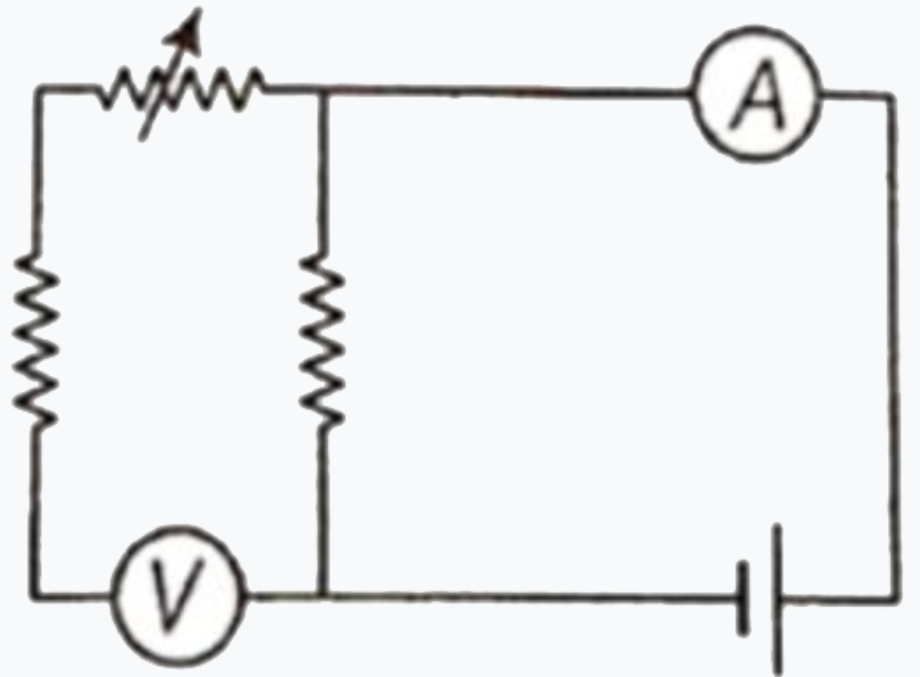 D
D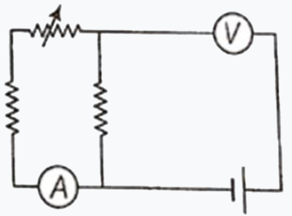
Express which of the following set ups can be used to verify Ohm's law.
A B
B C
C D
D
Express which of the following set ups can be used to verify
ohm's law?A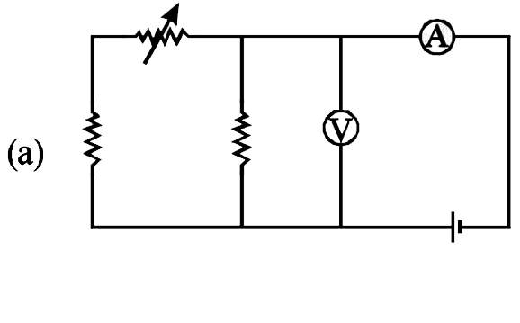 B
B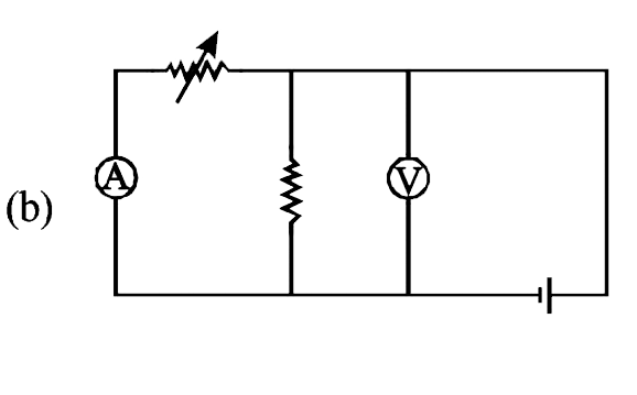 C
C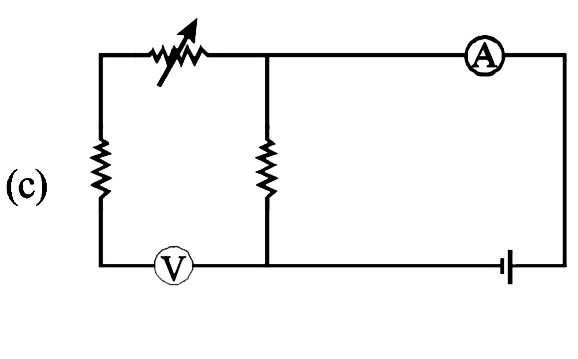 D
D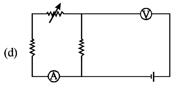
Which of the following circuits gives the correct value of resistance, when computed by using R=(V/I) where V and I are voltmeter and ammeter reading, respectively? The meters are not ideal.
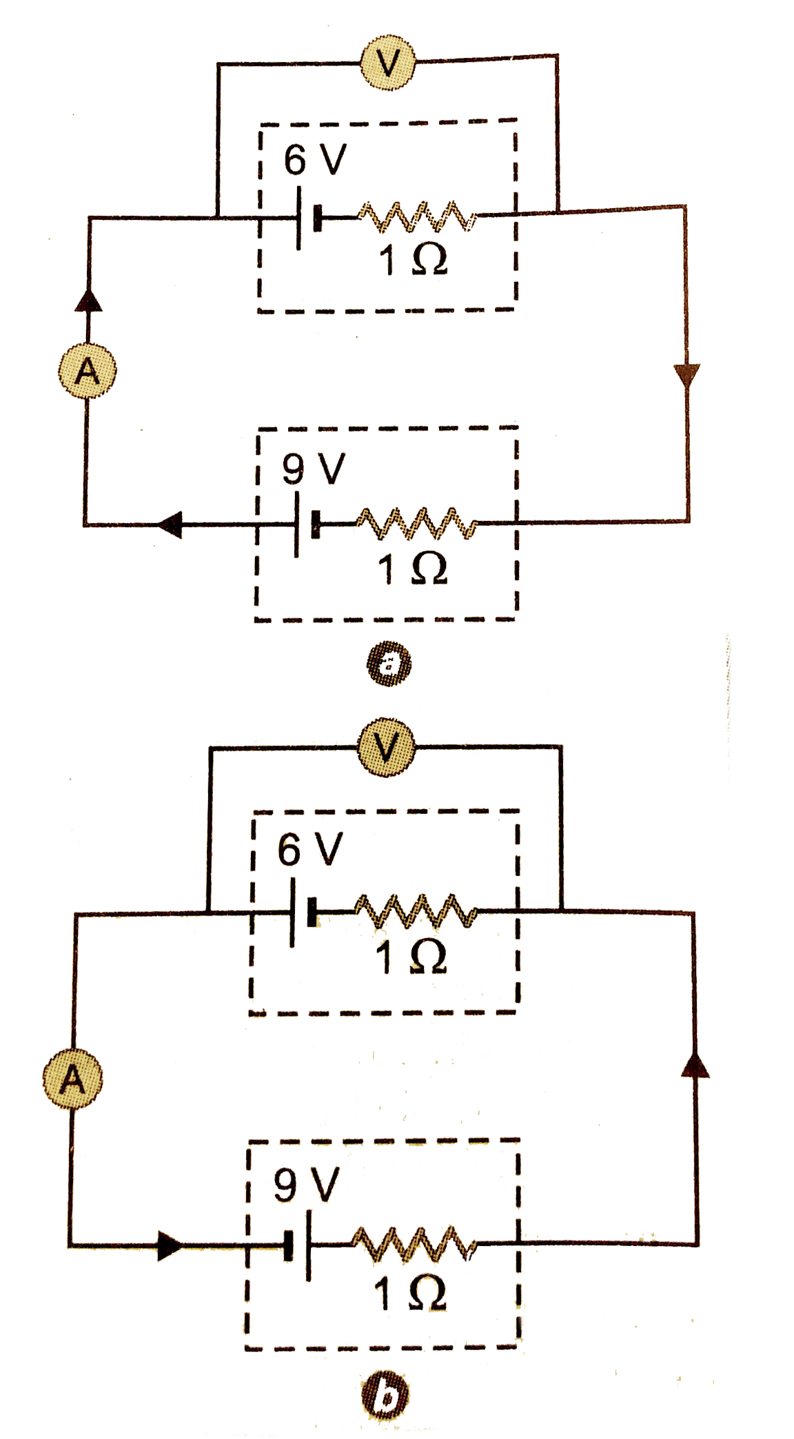
View SolutionIn the two electron circuit determine the readings of ideal ammeter (A) ideal voltmeter (V)
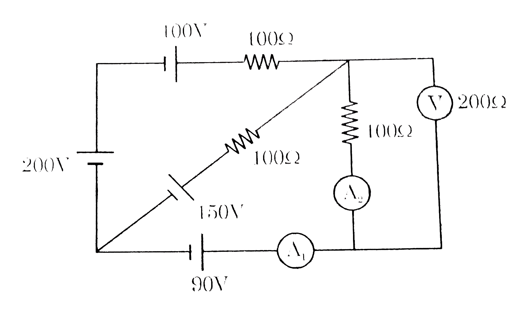
View SolutionWhich of the following options are CORRECT (ammeters are ideal).
View SolutionWhich of the following circuits gives the correct value of resistance, when computed by using R=(V/I) where V and I are voltmeter and ammeter reading, respectively? The meters are not ideal.
View SolutionWhich of the following options are CORRECT (ammeters are ideal).

View Solution

