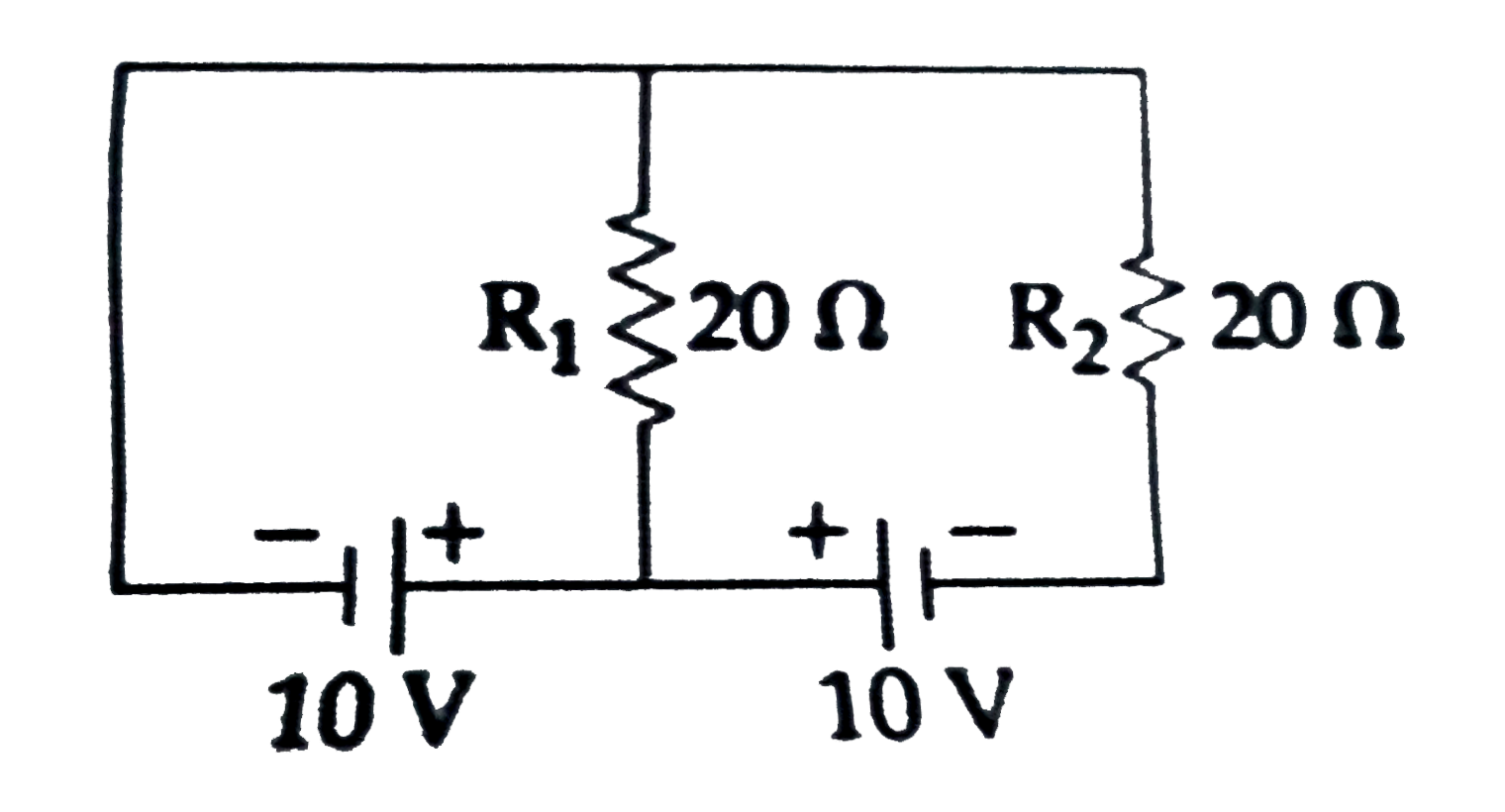
In the shown in the given figure, the resistances R1andR2 are respectively

14Ωand40Ω
40Ωand44Ω
40Ωand30Ω
14Ωand30Ω
The correct Answer is:A
Potential difference across 20Ω=20×1=20V=potential difference acrossR2.
Current in R2=0.5A
∴R2=20V0.5A=40Ω=40Ω
Potential difference across R1=69V−20V=49V
Current in R1=0.5A+2010+1A=3.5A
∴R1=493.5=14Ω
Topper's Solved these Questions
- CURRENT ELECTRICITYBOOK - NCERT FINGERTPS ENGLISHCHAPTER - CURRENT ELECTRICITYEXERCISE - CELLS, EMF, INTERNAL RESISTANCE
6 Videos
- CURRENT ELECTRICITYBOOK - NCERT FINGERTPS ENGLISHCHAPTER - CURRENT ELECTRICITYEXERCISE - KIRCHOFF S LAW
14 Videos
- CURRENT ELECTRICITYBOOK - NCERT FINGERTPS ENGLISHCHAPTER - CURRENT ELECTRICITYEXERCISE - ELECTRICAL ENERGY, POWER
8 Videos
- COMMUNITCATION SYSTEMSBOOK - NCERT FINGERTPS ENGLISHCHAPTER - COMMUNITCATION SYSTEMSEXERCISE - Assertion And Reason
30 Videos
- DUAL NATURE OF RADIATION AND MATTER BOOK - NCERT FINGERTPS ENGLISHCHAPTER - DUAL NATURE OF RADIATION AND MATTER EXERCISE - Assertion And Reason
15 Videos
Similar Questions
Three resistors R1,R2 and R3 are to be combined to form an electrical circuit as shown in the figure. It is found that when R1R2andR3 are put respectively in positions A, B and C, the effective resistance of the circuit is 70 ΩWhen R2,R3andR1 are put respectively in position A, B and C the effective resistance is 35Ω and when R3,R1andR2 are respectively put in the position A, B and C, the effective resistance is 42Ω
If R1,R2 andR3are put in series, the effective resistance will be
View SolutionThree resistors R1,R2 and R3 are to be combined to form an electrical circuit as shown in the figure. It is found that when R1R2andR3 are put respectively in positions A, B and C, the effective resistance of the circuit is 70 ΩWhen R2,R3andR1 are put respectively in position A, B and C the effective resistance is 35Ω and when R3,R1andR2 are respectively put in the position A, B and C, the effective resistance is 42Ω
If R1,R2andR3 are all connected in parallel, the effective resistance will be
View Solution
Knowledge Check
In the circuit shown in the given figure, the resistances R1andR2 are respectively
 A14Ωand40ΩB40Ωand44ΩC40Ωand30ΩD14Ωand30Ω
Three resistors R1,R2 and R3 are to be combined to form an electrical circuit as shown in the figure. It is found that when R1R2andR3 are put respectively in positions A, B and C, the effective resistance of the circuit is 70 ΩWhen R2,R3andR1 are put respectively in position A, B and C the effective resistance is 35Ω and when R3,R1andR2 are respectively put in the position A, B and C, the effective resistance is 42Ω
The resistanceR1:R2:R3are in the ratioA0.04380787037037B0.043101851851852C0.043854166666667D0.043819444444444Three resistors R1,R2 and R3 are to be combined to form an electrical circuit as shown in the figure. It is found that when R1R2andR3 are put respectively in positions A, B and C, the effective resistance of the circuit is 70 ΩWhen R2,R3andR1 are put respectively in position A, B and C the effective resistance is 35Ω and when R3,R1andR2 are respectively put in the position A, B and C, the effective resistance is 42Ω
If R1,R2andR3 are all connected in parallel, the effective resistance will beA37ΩB72ΩC50//7OmegaD607Ω
Three resistors R1,R2 and R3 are to be combined to form an electrical circuit as shown in the figure. It is found that when R1R2andR3 are put respectively in positions A, B and C, the effective resistance of the circuit is 70 ΩWhen R2,R3andR1 are put respectively in position A, B and C the effective resistance is 35Ω and when R3,R1andR2 are respectively put in the position A, B and C, the effective resistance is 42Ω
The resistanceR1:R2:R3are in the ratio
View SolutionIn the given circuit the cells have zero internal resistance. The currents (in Amperes) passing through resistance R1andR2 respectively, are :

View SolutionIn the given circuit the cells have zero internal resistance. The currents (in Amperes) passing through resistance R1andR2 respectively, are :

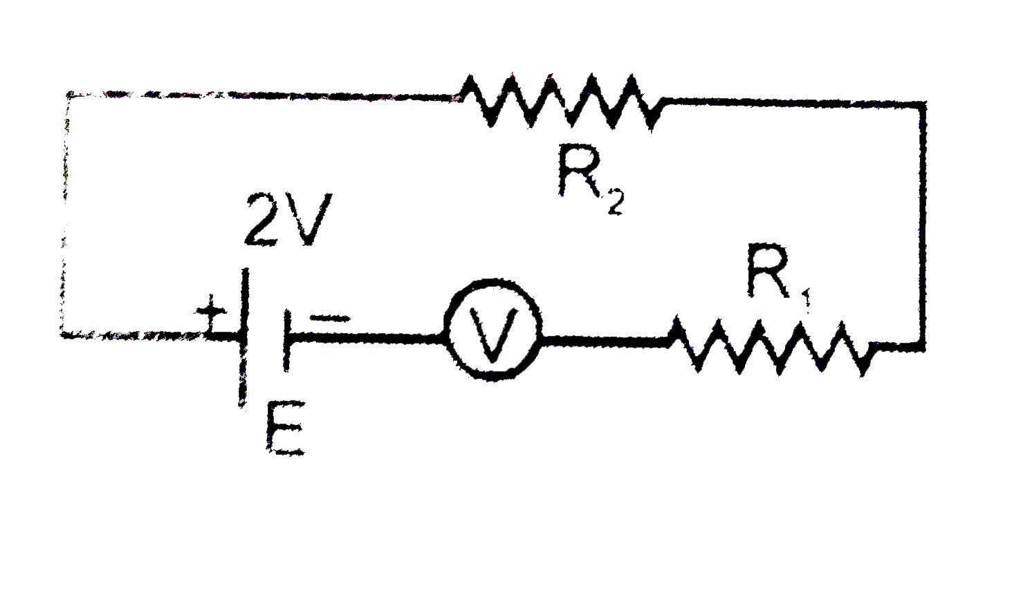
View SolutionA cell of e.m.f. 2V and negligible internal resistance is connected to resistor R1 and R2 as shown in the figure. The resistance of the Voltmeter R1 and R2 are 80Ω,40Ω and 80Ω respectively. The reading of the voltmeter is:-

View SolutionThree resistors R1,R2 and R3 are to be combined to form an electrical circuit as shown in the figure. It is found that when R1R2andR3 are put respectively in positions A, B and C, the effective resistance of the circuit is 70 ΩWhen R2,R3andR1 are put respectively in position A, B and C the effective resistance is 35Ω and when R3,R1andR2 are respectively put in the position A, B and C, the effective resistance is 42Ω
IfR_(1), R_(2)and R,_(3)are put in series, the effective resistance will be
View Solution
