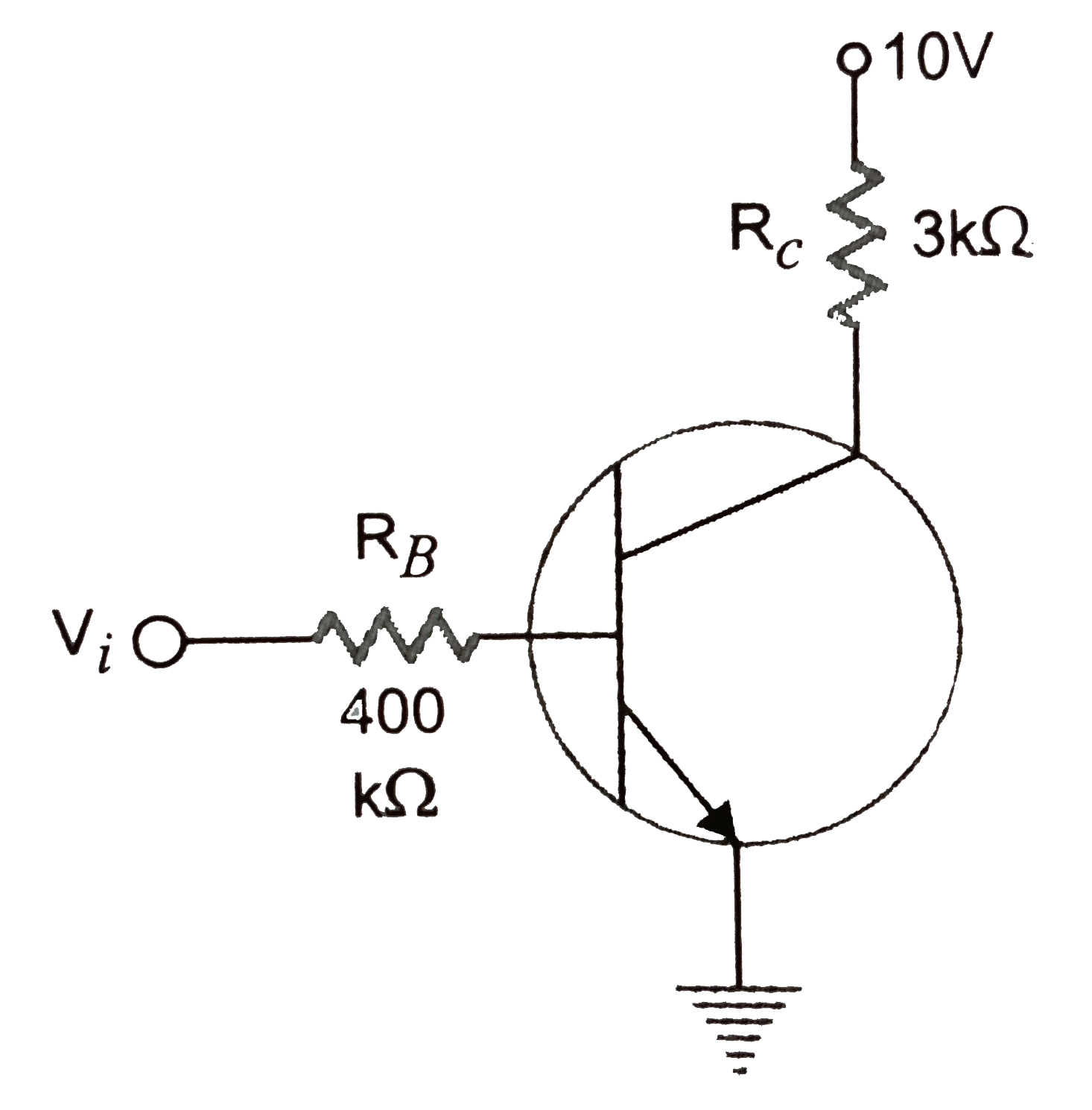
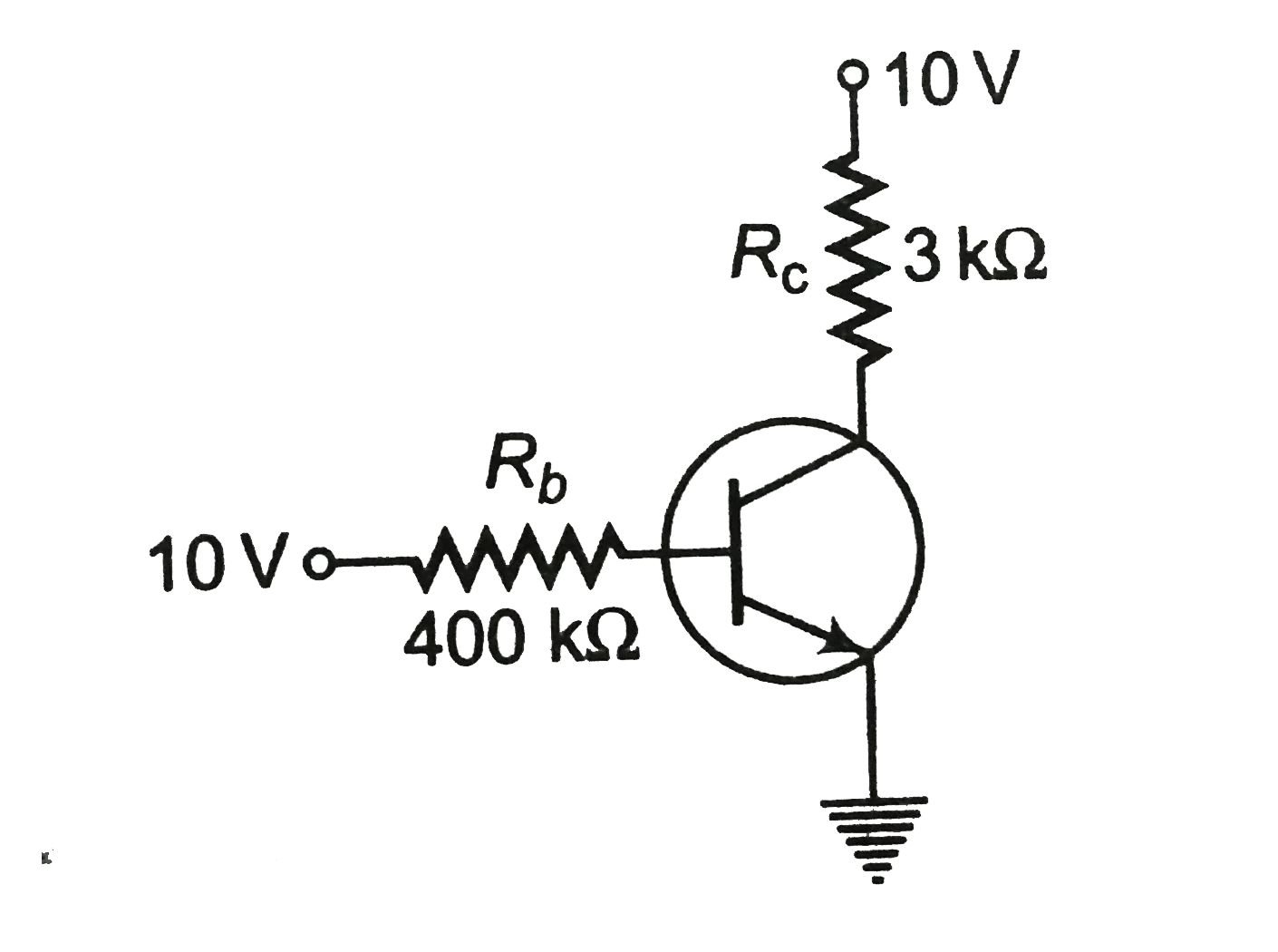
In the circuit shown in figure, when the input voltage of the base resistance is 10 V, Vbe is zero and Vce is also zero. Then
β=110
Ib=25μA
Ic=3.33mA
both (A) and (C )
The correct Answer is:D
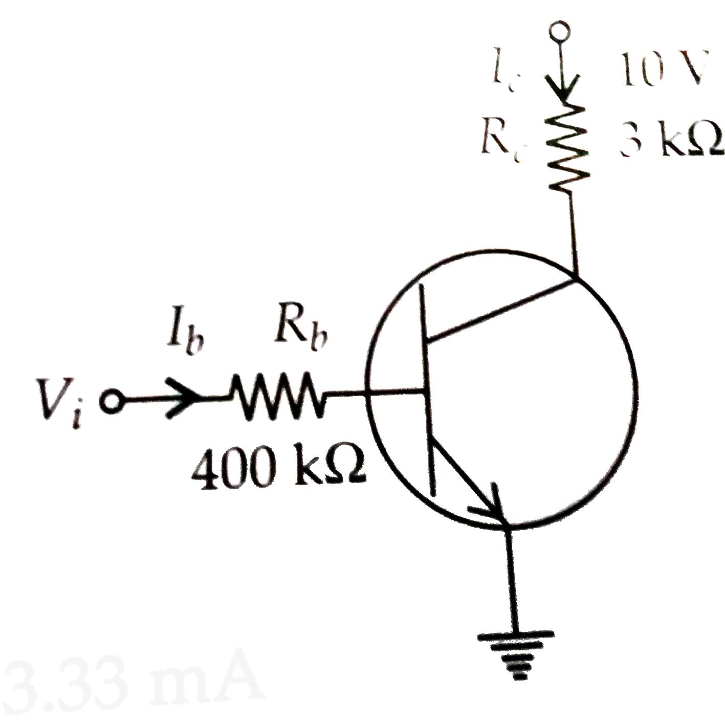
Given Vi=10 V, Rb=400kΩ=400×103Ω
Rc=3kΩ=3×10³Ω,Vbe=0,Vce=0,VCC=10V
As Vi−Vbe=RbIb
∴10−0=(400×103)Ib
lb=10400×103
=25×10−6A=25μA
VCC=Vce=IcRc
Ic=103×103=3.33×10−3=3.33mA
β=IcIb=3.33×10−325×10−6=133
Topper's Solved these Questions
- BOOK - NCERT FINGERTPS ENGLISHCHAPTER - SEMICONDUCTOR ELECTRONICS : MATERIALS , DEVICES AND SIMPLE CIRCUITS EXERCISE - NCERT8videos
SEMICONDUCTOR ELECTRONICS : MATERIALS , DEVICES AND SIMPLE CIRCUITS
- BOOK - NCERT FINGERTPS ENGLISHCHAPTER - SEMICONDUCTOR ELECTRONICS : MATERIALS , DEVICES AND SIMPLE CIRCUITS EXERCISE - ASSERTION & REASON15videos
SEMICONDUCTOR ELECTRONICS : MATERIALS , DEVICES AND SIMPLE CIRCUITS
- BOOK - NCERT FINGERTPS ENGLISHCHAPTER - SEMICONDUCTOR ELECTRONICS : MATERIALS , DEVICES AND SIMPLE CIRCUITS EXERCISE - Assertion And Reason15videos
SEMICONDUCTOR ELECTRONICS : MATERIALS , DEVICES AND SIMPLE CIRCUITS
- BOOK - NCERT FINGERTPS ENGLISHCHAPTER - RAY OPTICS AND OPTICAL INSTRUMENTSEXERCISE - NCERT Exemplar11videos
RAY OPTICS AND OPTICAL INSTRUMENTS
- BOOK - NCERT FINGERTPS ENGLISHCHAPTER - WAVE OPTICSEXERCISE - Assertion And Reason15videos
WAVE OPTICS
Similar Questions
Knowledge Check
- Question 1 - Select One
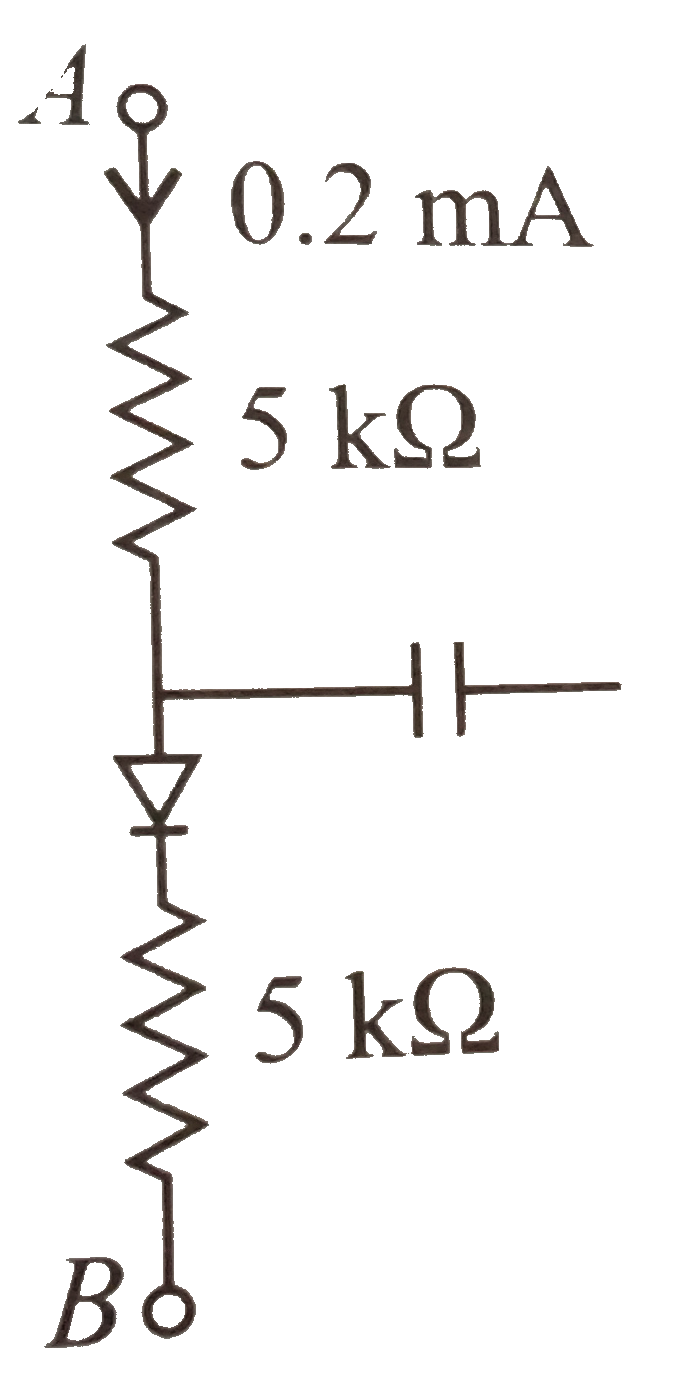
In the circuit shown in figure, if the A diode forward voltage drop is 0.3 V, the voltage difference between A and B is
 A1.3 VB2.3 VC0D0.5 V
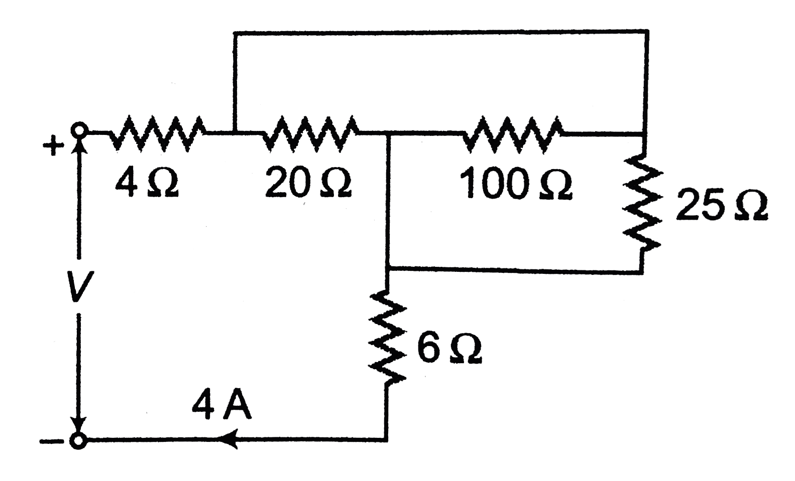
In the circuit shown in figure , V must be
 View Solution
In the circuit shown in figure when the input voltage of the base resistance is 10 V . Find the values of Ib,Icandβ .
 View Solution
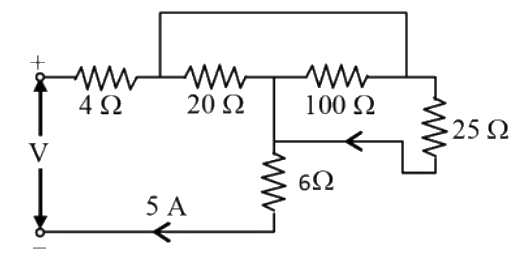
In the circuit shown in the figure , V must be -
 View Solution
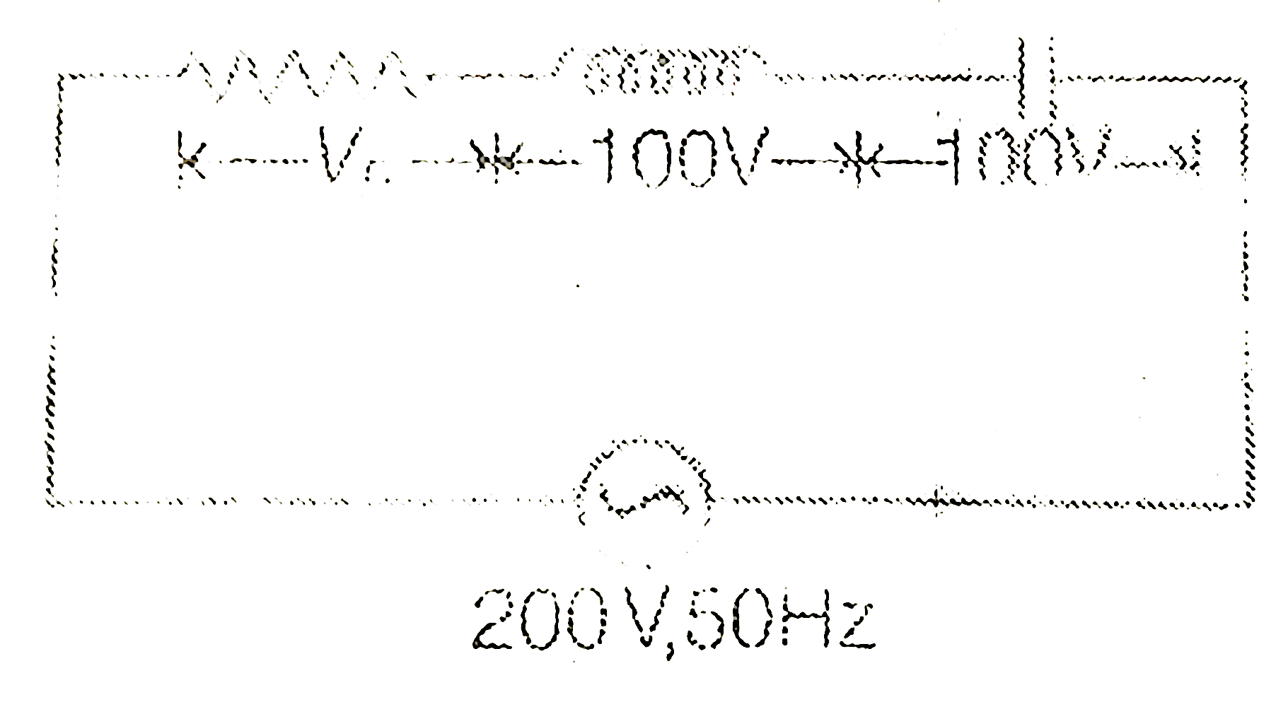
In the circuit shown in figure value of VR is
 View Solution
In the circuit shown in figure find Vab at 1s
 View Solution
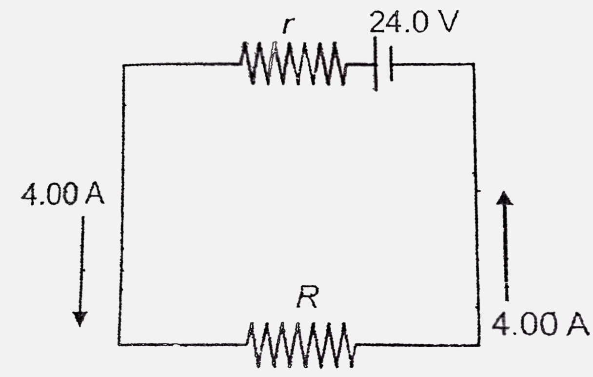
Consider the circuit shown in Figure . Ther terminal voltage of the 24.0 V battery is 21.2V. What are
(a) The internal resistance r of the battery and
(b) The resistance R of the circuit resistor ?
 View Solution
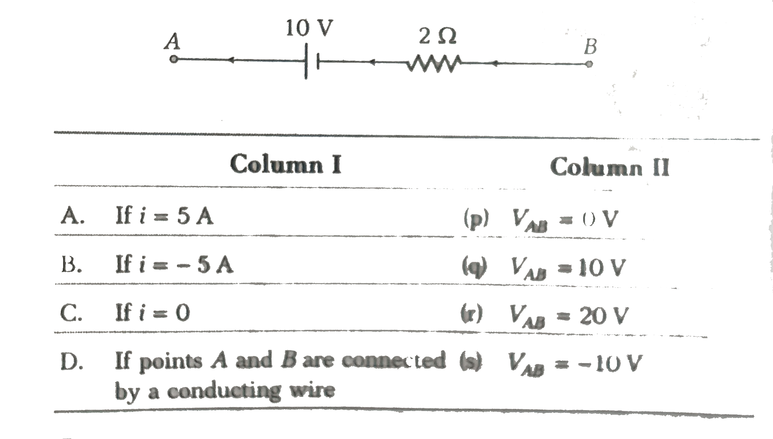
In the part of circuit shown in figure, match the following two columns for VAB
 View Solution


