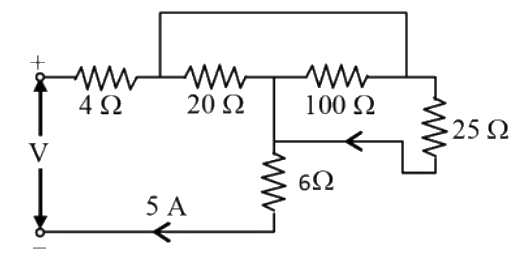
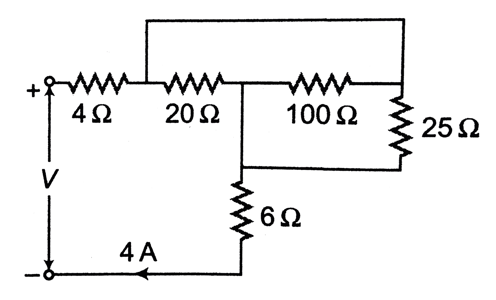
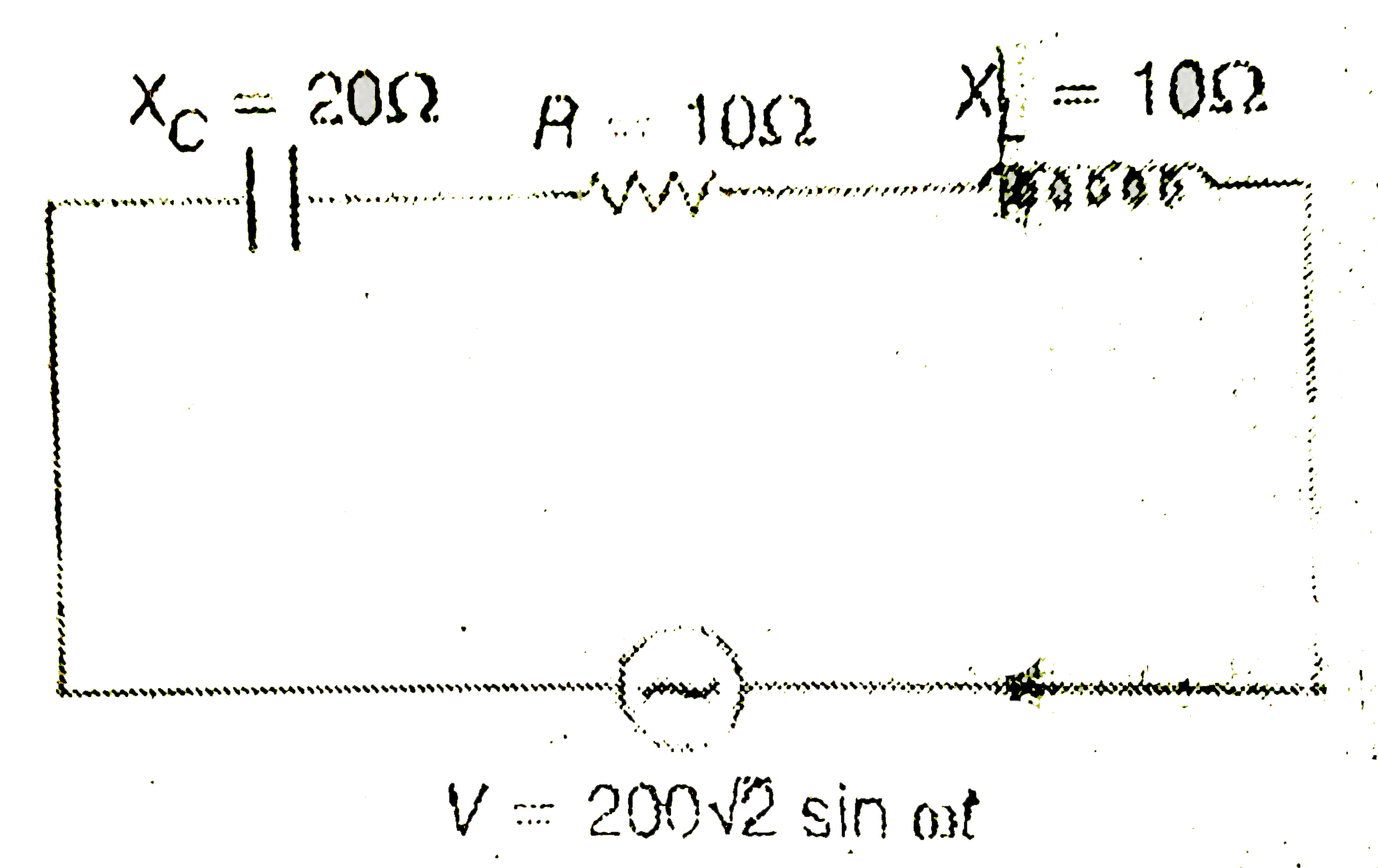
In the circuit shown in figure , V must be
A
50V
B
80V
C
100V
D
1290V
Video Solution
Text Solution
The correct Answer is:B
100Ω,25Ω and 20Ω are in parallel.
Their net resistance is 10Ω
∴Rnet=4Ω+10Ω+6Ω=20Ω
Hence the main current
i=ERnet=1A
Current through either of the resistance
isi3or13A
∴V=iR=(13)(9)=3V
|
Topper's Solved these Questions
- CURRENT ELECTRICITYBOOK - DC PANDEY ENGLISHCHAPTER - CURRENT ELECTRICITYEXERCISE - Level 2 More Than One Correct
10 Videos
- CURRENT ELECTRICITYBOOK - DC PANDEY ENGLISHCHAPTER - CURRENT ELECTRICITYEXERCISE - Level 2 Comprehension Example Type
2 Videos
- CURRENT ELECTRICITYBOOK - DC PANDEY ENGLISHCHAPTER - CURRENT ELECTRICITYEXERCISE - Level 1 Subjective
53 Videos
- COMMUNICATION SYSTEMBOOK - DC PANDEY ENGLISHCHAPTER - COMMUNICATION SYSTEMEXERCISE - Subjective
11 Videos
- ELECTROMAGNETIC INDUCTIONBOOK - DC PANDEY ENGLISHCHAPTER - ELECTROMAGNETIC INDUCTIONEXERCISE - Medical entrances gallery
25 Videos
Similar Questions
Knowledge Check
In the circuit shown in figure, if the A diode forward voltage drop is 0.3 V, the voltage difference between A and B is
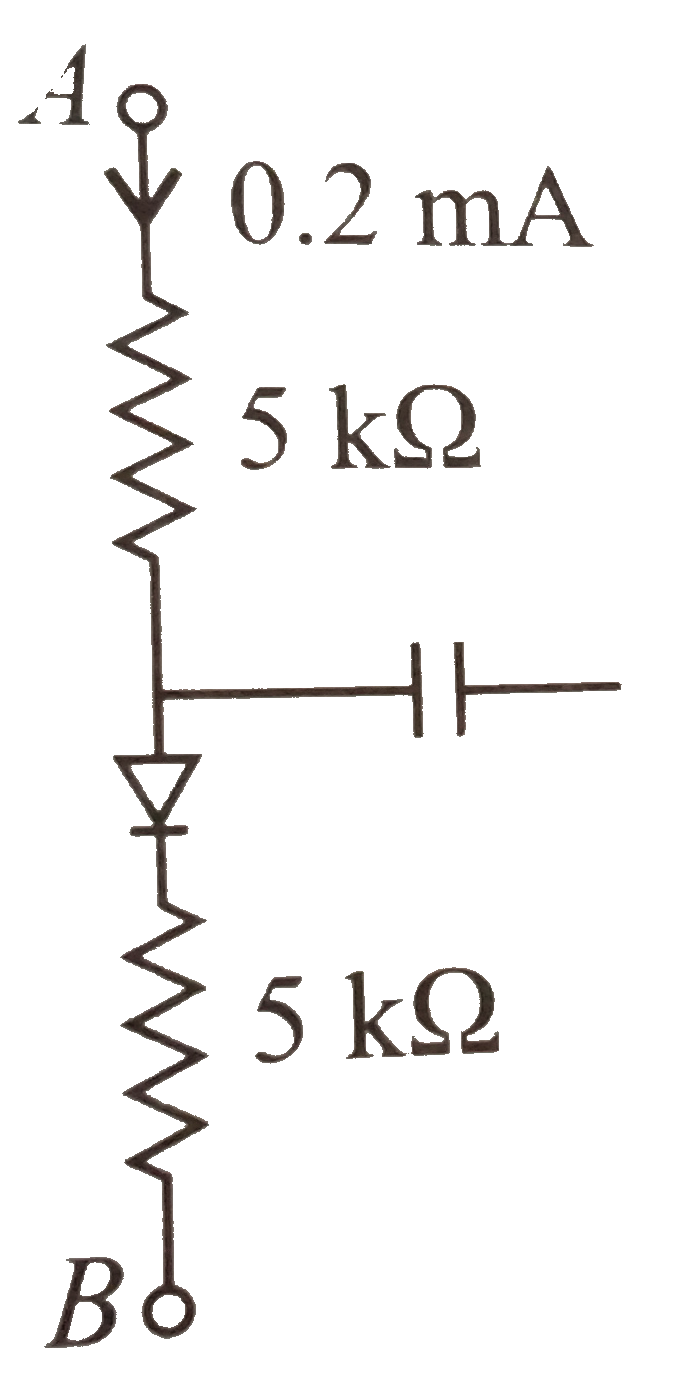 A1.3 VB2.3 VC0D0.5 V
For the circuit shown in figure
View SolutionIn the circuit shown in the figure,
View SolutionIn the circuit shown in the figure
 .
.
View SolutionIn the two circuits shown in figure
View SolutionTo get an output 1 from the circuit shown in figure the input must be :

View SolutionTo get an output of 1 form the circuit shown in figure the input must be :-
_E01_514_Q01.png)
View SolutionIn LCR circuit as shown in figure
View Solution

