Phasor diagram of a series AC circuit is shown in figureure. Then,
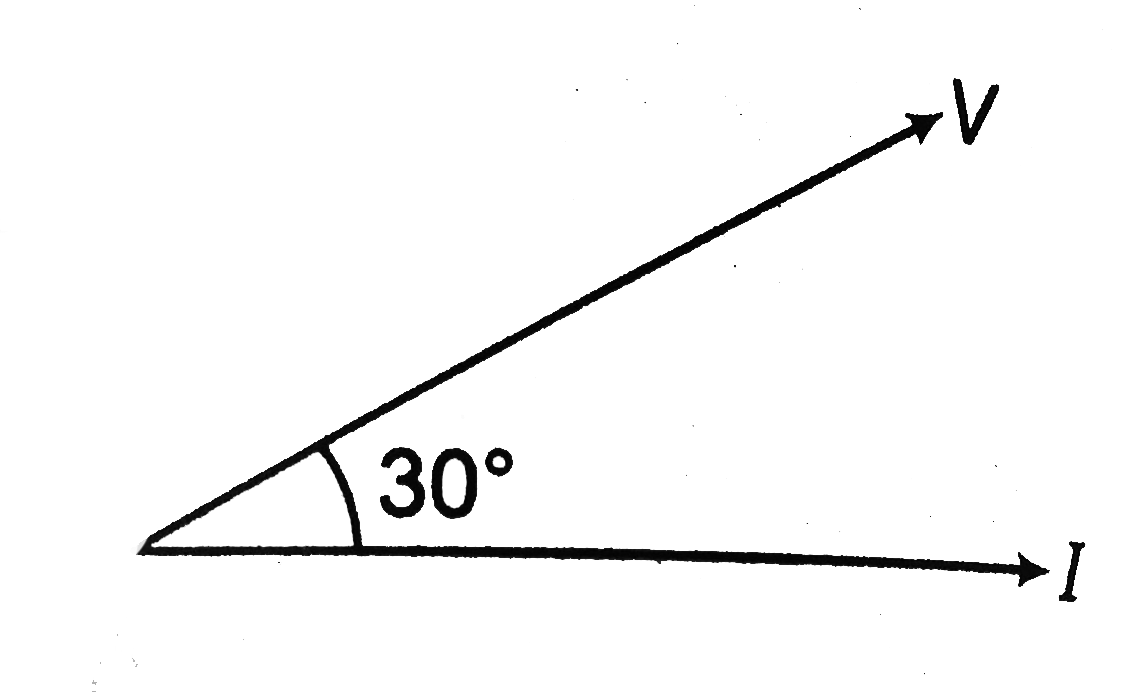
The circuit must be containing resistor and capacitor only
The circuit must be containing resistor and inductor only
The circuit must be containing all three elements L, C and R
The circuit cannot have only capacitor and inductor
The correct Answer is:D
In case of only capacitor and inductor phase difference between current and voltage should be 90∘
Topper's Solved these Questions
- ALTERNATING CURRENTBOOK - DC PANDEY ENGLISHCHAPTER - ALTERNATING CURRENTEXERCISE - Level - 1 Subjective
6 Videos
- ALTERNATING CURRENTBOOK - DC PANDEY ENGLISHCHAPTER - ALTERNATING CURRENTEXERCISE - Level- 2 Single Correct
18 Videos
- ALTERNATING CURRENTBOOK - DC PANDEY ENGLISHCHAPTER - ALTERNATING CURRENTEXERCISE - Level 1 Assertion-Reason
11 Videos
- ATOMSBOOK - DC PANDEY ENGLISHCHAPTER - ATOMSEXERCISE - MEDICAL ENTRANCES GALLERY
42 Videos
Similar Questions
Knowledge Check
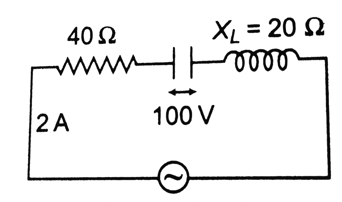
In the series LCR circuit shown the impedance is
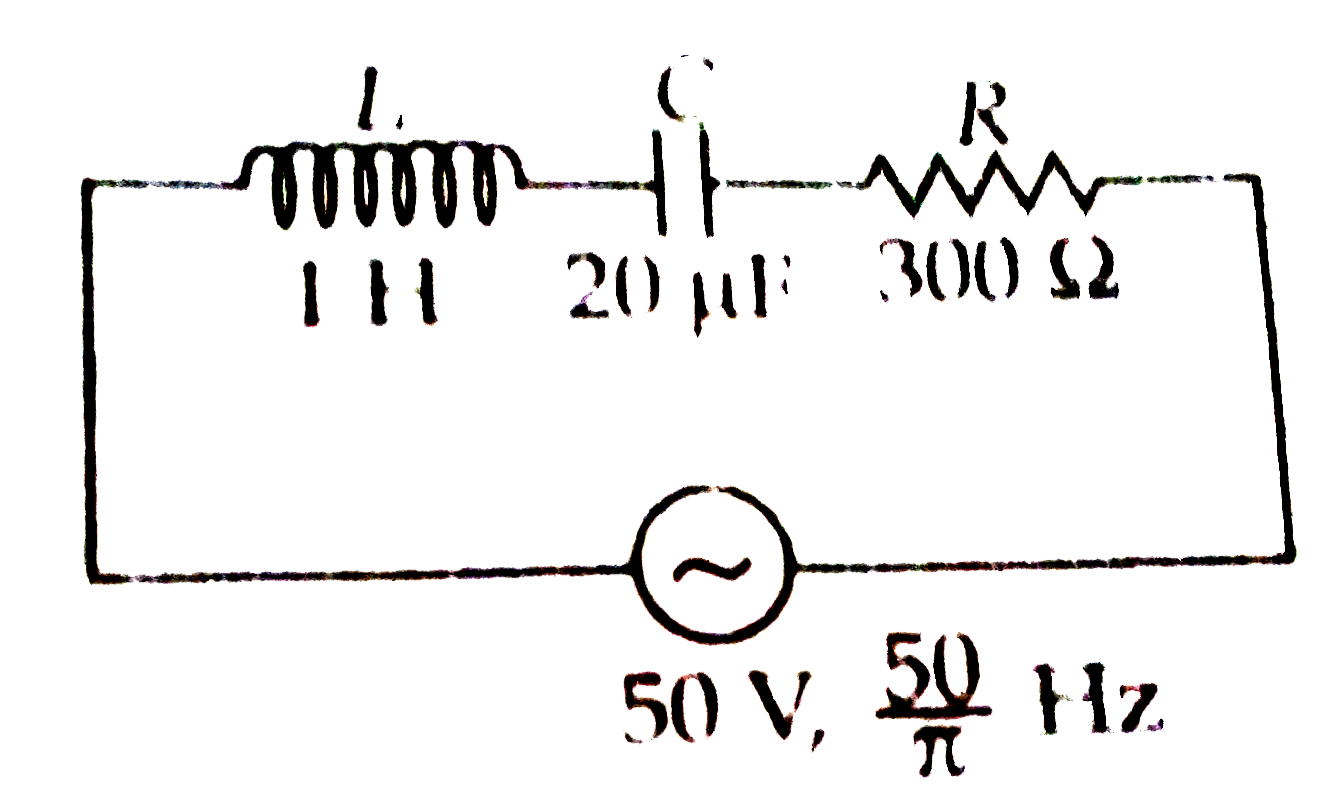 A200ΩB100ΩC300ΩD500Ω
(a) Draw graphs showing the variations of inductive reactnace and capacitive reactance with frequency of the applied ac source .
(b) Draw the phasor diagram for a series RC circuit connected to an ac source.
(c ) An alternating voltage of 220 V is applied across a device X , a current of 0.25 A flows , which lag behind the applied voltage in phase by π2 radian . If the same voltage is applied across another device Y , the same current flows but now it is in phase with the applied voltage .
(i) Name the devices X and Y.
(ii) Calculate the current flowing in the circuit when the same voltage is applied across the series combination of X and Y.

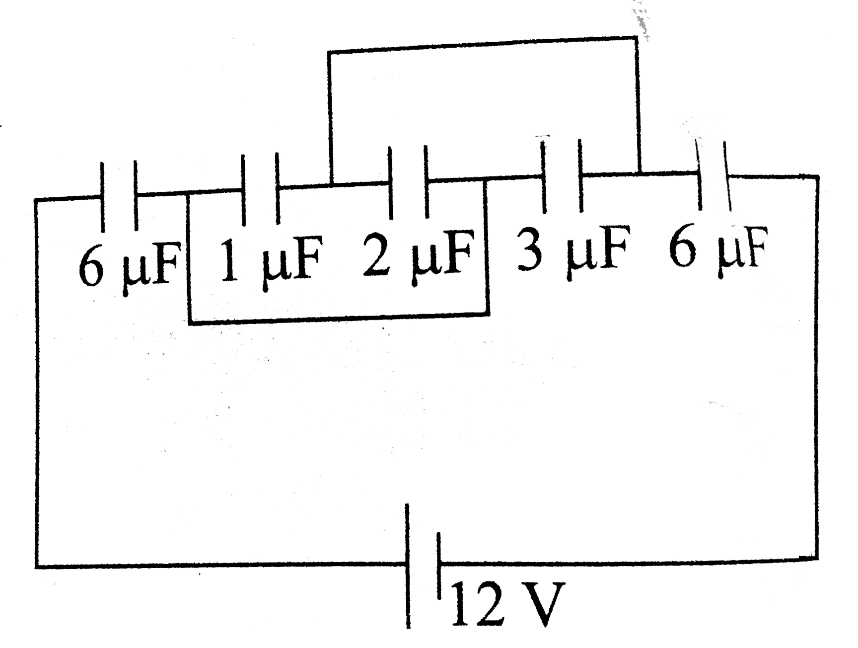
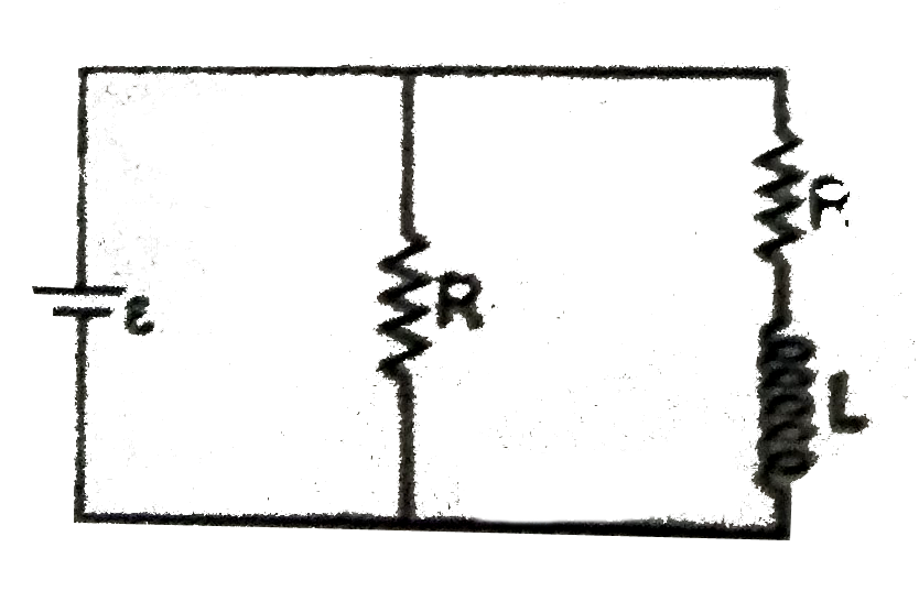
View SolutionIn the circuit diagram shown in Figure,
 .
.
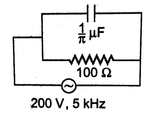
View SolutionA signal generator supplies a sine wave of 200V,5kHz to the circuit shown in the figureure. Then, choose the wrong statement.
 .
.
View SolutionIn the series LCR circuit shown the impedance is

View SolutionIn the circuit diagram shown
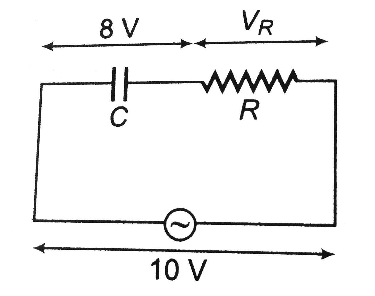
View SolutionIn a series C−R circuit shown in figureure, the applied voltage is 10V and the voltage across capacitor is found to8V. The voltage across R, and the phase difference between current and the applied voltage will respectively be
 .
.
View SolutionIn a series C−R circuit shown in figureure, the applied voltage is 10V and the voltage across capacitor is found to8V. The voltage across R, and the phase difference between current and the applied voltage will respectively be
 .
.
View Solution

 .
.