In the LCR circuit shown in figure, the ac driving voltage is V=Vmsinωt
(a) Write down the equation of motion for q(t)
(b) At t=t0, the voltage source stops and R is short circuited. Now write down how much energy is stored in each of L and C.
(c) Describe subsequent motion of charges.
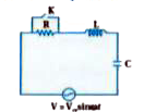
(a) Consider the L-C-R circuit as shown in figure.
V=Vmsinωt is given, let instantaneous current is i.
Applying Kirchhoff.s second law for closed loop,
VR+VL+VC=Vmsinωt
iR+Ldidt+qC−Vmsinωt=0 ….(1)
but i=dqdt⇒didt=d2qdt2
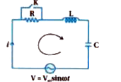
From equation (1) ,
Rdqdt+Ld2qdt2+qC=Vmsinωt
∴Ld2qdt2+Rdqdt+qC=Vmsinωt
This is the required equation of variation (motion) of charge.
(b)Let q=qmsin(ωt+ϕ)
∴q=−qmcos(ωt+ϕ)
integrating with respect to time,
dqdt=dqmdtωsin(ωt+ϕ)
∴i=imsin(ωt+ϕ)[∵im=qmω]
im=VmZ=Vm√R2+(XC−XL)2
∴i=Vm√R2+(XC−XL)2ωsinωt
ϕ=tan−1(XC−XLR)
When R is short circuited at t=t0 , energy is stored in L and C .
UL=12Li2=12L⎡⎢
⎢⎣Vm√R2+(XC−XL)2⎤⎥
⎥⎦2sin2(ωt0+ϕ)
UC=12.q2C=12C[q2mcos2(ωt0+ϕ)]
=12C⎡⎢
⎢⎣Vm√R2+(XC−XL)2⎤⎥
⎥⎦2
=12C[imω]2cos2(ωt0+ϕ)
=i2m2Cω2cos2(ωt0+ϕ)[∵im=ωqm]
=12C⎡⎢
⎢⎣Vm√R2+(XC−XL)2⎤⎥
⎥⎦2
cos2(ωt0+ϕ)ω2
=12Cω2⎡⎢
⎢⎣Vm√R2+(XC−XL)2⎤⎥
⎥⎦2
cos2(ωt0+ϕ)
When R is short circuited, the circuit becomes an L-C oscillator. The capacitor will go on discharging and all energy will go to L and back and forth. Hence, there is oscillation of energy from electrostatic to magnetic and magnetic to electrostatic.
Topper's Solved these Questions
- ALTERNATING CURRENTS BOOK - KUMAR PRAKASHANCHAPTER - ALTERNATING CURRENTS EXERCISE - SECTION-D MCQs (DARPAN BASED ON TEXTBOOK)
188 Videos
- ALTERNATING CURRENTS BOOK - KUMAR PRAKASHANCHAPTER - ALTERNATING CURRENTS EXERCISE - SECTION-D MCQs (COMPETITIVE EXAMS)
64 Videos
- ALTERNATING CURRENTS BOOK - KUMAR PRAKASHANCHAPTER - ALTERNATING CURRENTS EXERCISE - SECTION-C NCERT EXEMPLAR ( Short Answer)
6 Videos
- ATOMSBOOK - KUMAR PRAKASHANCHAPTER - ATOMSEXERCISE - Section-D -MCQs asked in GUJCET / Board Exam
34 Videos
Similar Questions
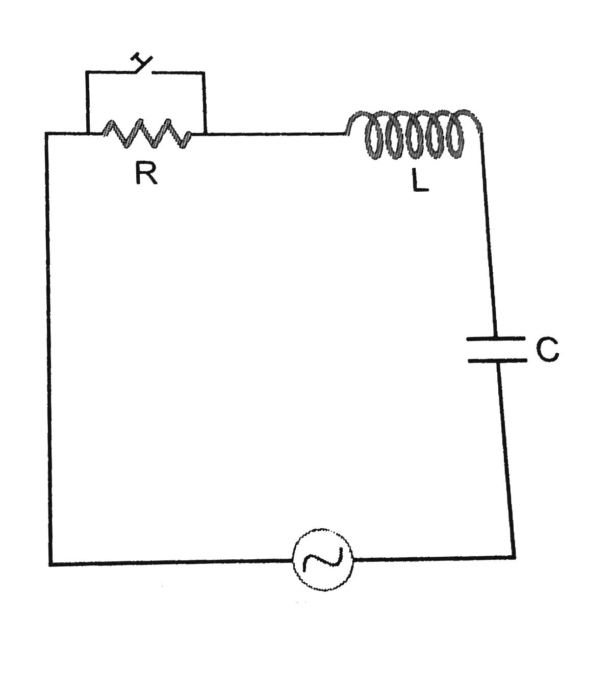
In the LCR circuit shown in Fig., the ac driving voltage is υ=υmsinωt.
(i) Write down the equation of motion for q (t).
(ii) At t=t0, the source stops and R is short circuited.
Now write down how much energy is stored in each of L and C.
(iii) Describe subsequent motion of charges.
View SolutionIn the LCR circuit shown in Fig., the ac driving voltage is υ=υmsinωt.
(i) Write down the equation of motion for q (t).
(ii) At t=t0, the source stops and R is short circuited.
Now write down how much energy is stored in each of L and C.
(iii) Describe subsequent motion of charges.

View Solution
Knowledge Check
In series LCR circuit, the voltages across R, L and C shown in figure. The voltage of applied source is
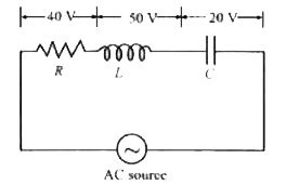 A110 voltB10 voltC50 voltD70 volt
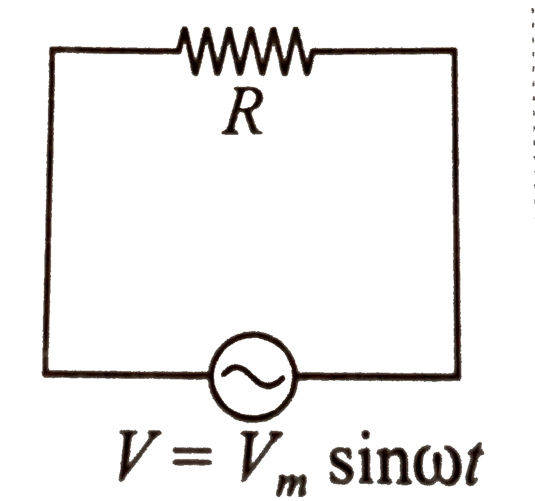
An ac source of voltage V=Vmsinωt is connected across the resistance R as shown in figure. The phase relation between current and voltage for this circuit is
 Aboth are in phaseBboth are out of phase by 90∘Cboth are out of phase by 120∘Dboth are out of phase by 180∘
An ac source of voltage V=Vmsinωt is connected across the resistance R as shown in figure. The phase relation between current and voltage for this circuit is
 Aboth are in phaseBboth are out of phase by 90∘Cboth are out of phase by 120∘Dboth are out of phase by 180∘
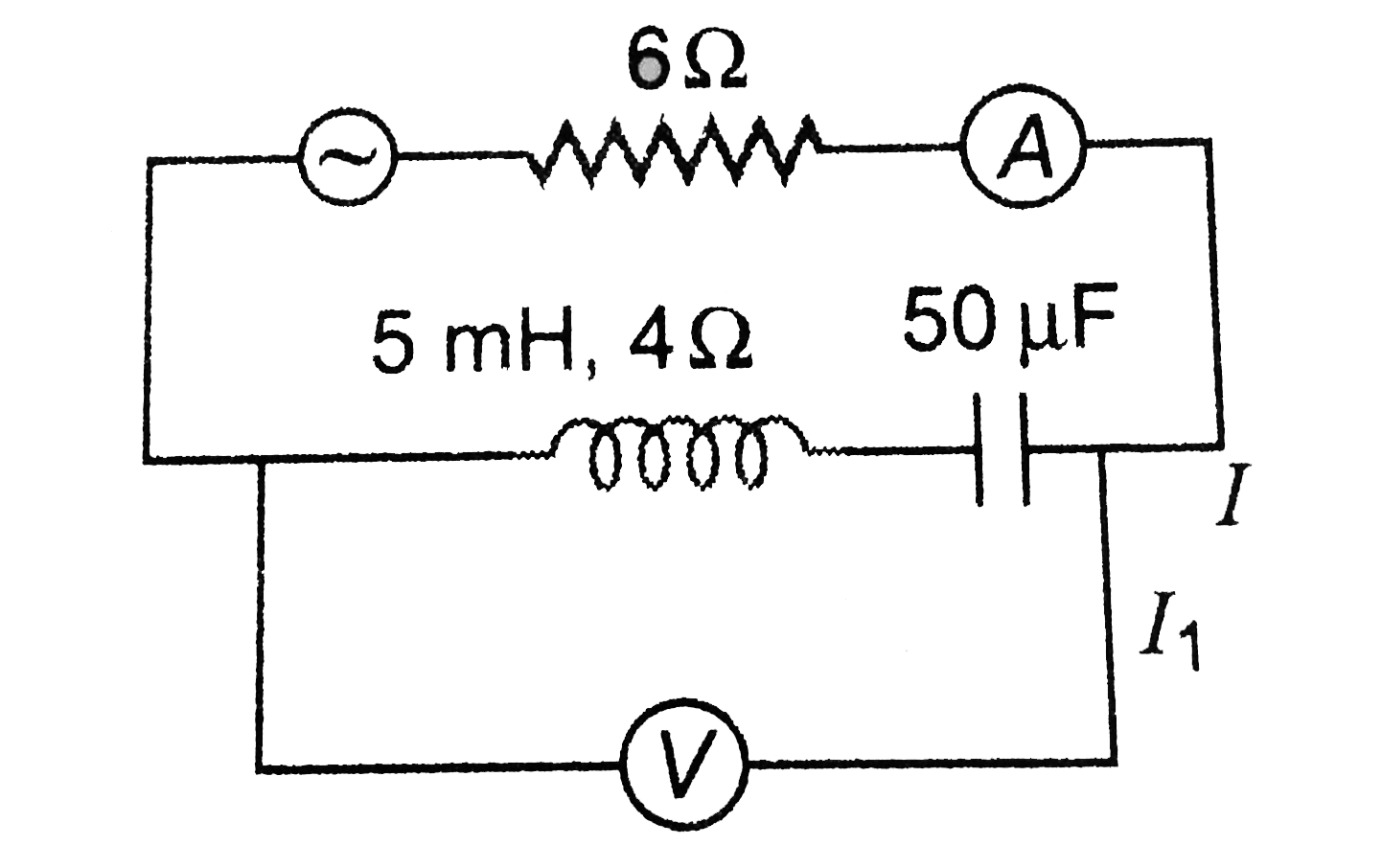
In the circuit shown in figure, the AC source gives a voltage V = 20 cos(2000 t ) . Neglecting source resistance, the voltmeter and ammeter readings will be (approximately)
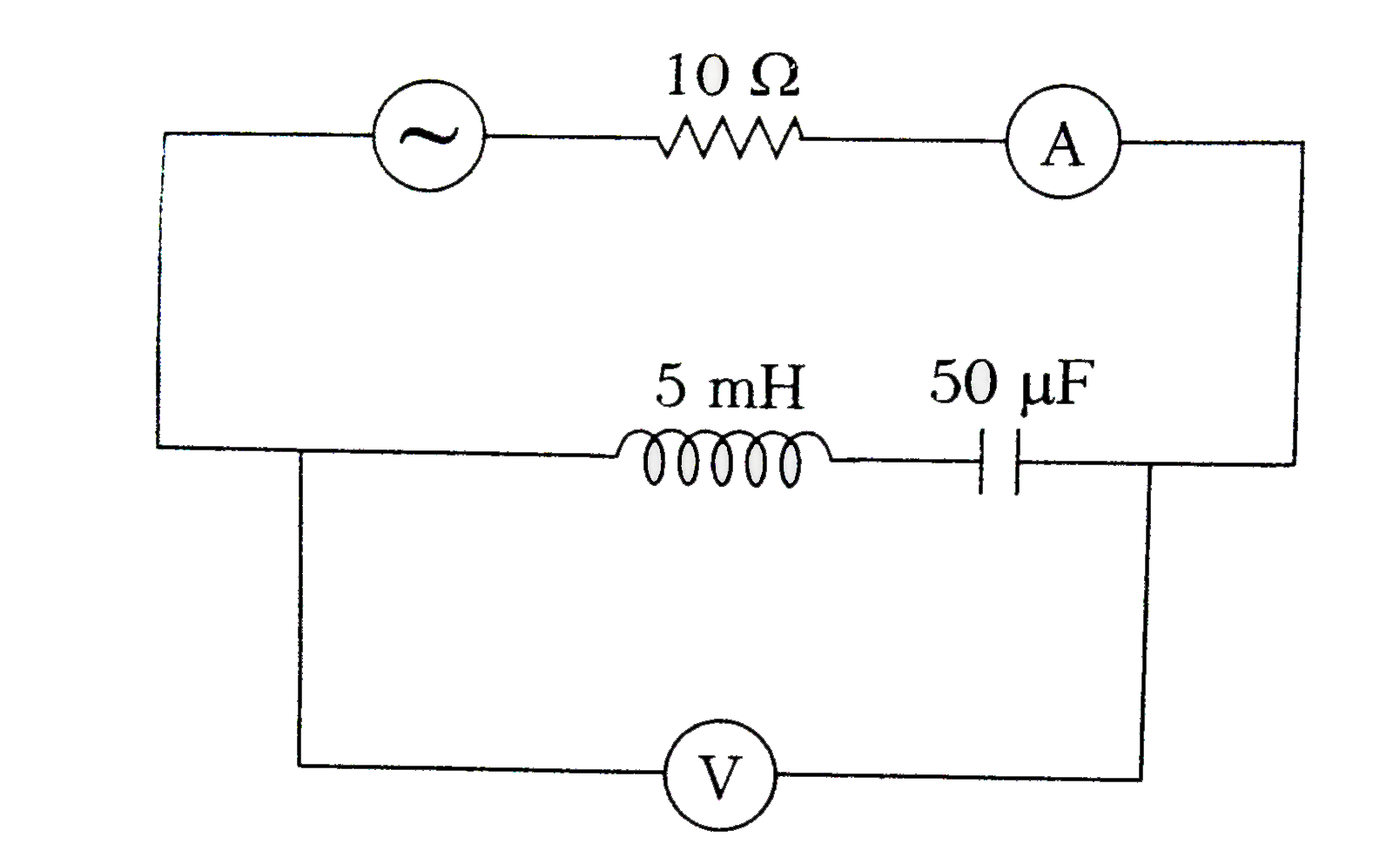
View SolutionIn the circuit shown in figureure the AC source gives a voltage V=20cos(2000t). Neglecting source resistance, the voltmeter and and ammeter readings will be
 .
.
View SolutionIn the circuit shown in figure, the AC source gives a voltage V = 20 cos(2000 t ) . Neglecting source resistance, the voltmeter and ammeter readings will be (approximately)

View SolutionA seris LR circuit is connected to a voltage source with V(t)=V0sinωt. After very large time, current 1(t) behaves as
(t0>>LR):
View SolutionIn the circuit shown in figure the AC source gives a voltage V=20cos(2000t). Neglecting source resistance, the voltmeter and and ammeter readings will be
 .
.
View Solution
