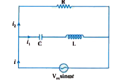
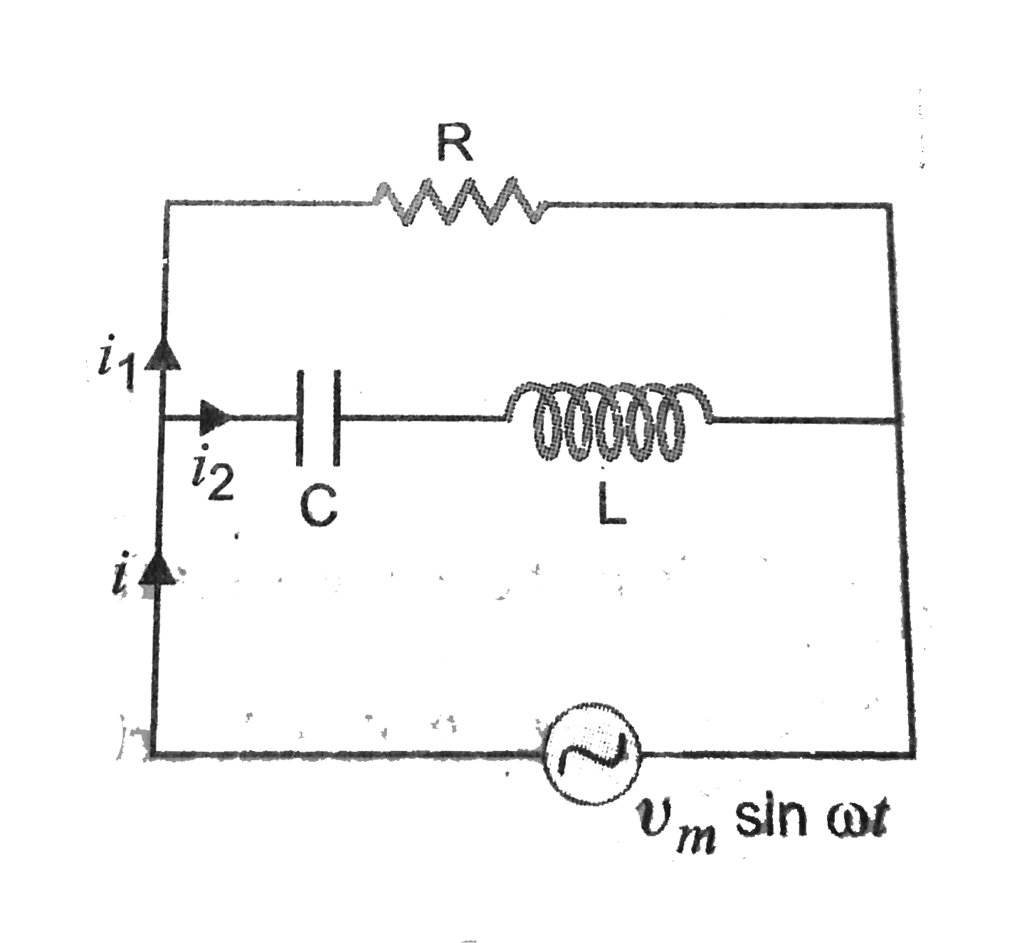
Consider the LCR circuit shown in figure. Find the net current i and the phase of i. Show that i=VZ . Find the impedence Z for this circuit.
Text Solution
Let i is the total current from the source. It is divided into two part i1 through R and i2 through series combination of C and L.
so, i=i1+i2
but V=Vmsinωt
∴i1R=Vmsinωt
∴i1=VmsinωtR....(1)
If q2 is charge on the capacitor at any time t, then
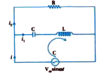
By using Kirchhoff.s second law,
VC+VL−Vmsinωt=0
q2C+Ldi2dt−Vmsinωt=0
∴q2C+Ld2q2dt2=Vmsinωt...(2)
[∵i2=dq2dt⇒di2dt=d2q2dt2]
Suppose , q2=qmsin(ωt+ϕ)
∴dq2dt=qmωcos(ωt+ϕ) ...(3)
d2q2dt=−qmω2sin(ωt+ϕ)
Putting this value in equation (2),
qmsin(ωt+ϕ)C−Lqmω2sin(ωt+ϕ)=Vmsinωt
qmsin(ωt+ϕ)[1C−Lω2]=Vmsinωt
If ϕ=0 and (1C−Lω2)>0, then
qm=Vm(1C−Lω2)...(4)
From equation (3) ,
i2=qmωcos(ωt+ϕ)[∵dq2dt=i2] ...(5)
from equation (4),
i2=Vm(1C−Lω2)ωcos(ωt+ϕ)
Taking ϕ=0∘
i2=Vmωcosωt1ωC−Lω...(6)
From equation (1) and (5) , we find that i1 and i2 are out of phase by π2.
Now i1+i2=VmsinωtR+Vm1ωC−Lωcosωt
Here VmR=A=Ccosϕ
Vm1ωC−ωL=B=Csinϕ
i1+i2=Ccosϕsinωt+Csinϕcosωt
i=Csin(ωt+ϕ)...(7)
[∵ sin A cos B + cos A sin B = sin (A+B)]
A2+B2=C2cos2ϕ+C2sin2ϕ
∴A2+B2=C2
∴C=√A2+B2
=C=⎡⎢
⎢
⎢⎣V2mR2+V2m(1ωC−Lω)2⎤⎥
⎥
⎥⎦1/2 ...(8)
tan ϕ=BA
∴ϕ=tan−1(BA)
ϕ=tan−1(R1/(ωC)−ωL)
Now i=i1+i2
∴i=⎡⎢
⎢
⎢⎣V2mR2+V2m(1ωC−ωL)2⎤⎥
⎥
⎥⎦1/2sin(ωt+ϕ) ...(9)
From equation (8) and
ϕ=tan−1⎡⎣R1ωC−ωL⎤⎦
Now we know that ,
I=VR[R=Zsin(ωt+ϕ)]
∴i=VZsin(ωt+ϕ) ...(10)
Comparing equation (9) and (10) ,
iV=1Z=⎡⎢
⎢
⎢⎣1R2+1(1ωC−ωL)2⎤⎥
⎥
⎥⎦1/2
This is the necessary impendance of the circuit.
|
Topper's Solved these Questions
- ALTERNATING CURRENTS BOOK - KUMAR PRAKASHANCHAPTER - ALTERNATING CURRENTS EXERCISE - SECTION-D MCQs (DARPAN BASED ON TEXTBOOK)
188 Videos
- ALTERNATING CURRENTS BOOK - KUMAR PRAKASHANCHAPTER - ALTERNATING CURRENTS EXERCISE - SECTION-D MCQs (COMPETITIVE EXAMS)
64 Videos
- ALTERNATING CURRENTS BOOK - KUMAR PRAKASHANCHAPTER - ALTERNATING CURRENTS EXERCISE - SECTION-C NCERT EXEMPLAR ( Short Answer)
6 Videos
- ATOMSBOOK - KUMAR PRAKASHANCHAPTER - ATOMSEXERCISE - Section-D -MCQs asked in GUJCET / Board Exam
34 Videos
Similar Questions
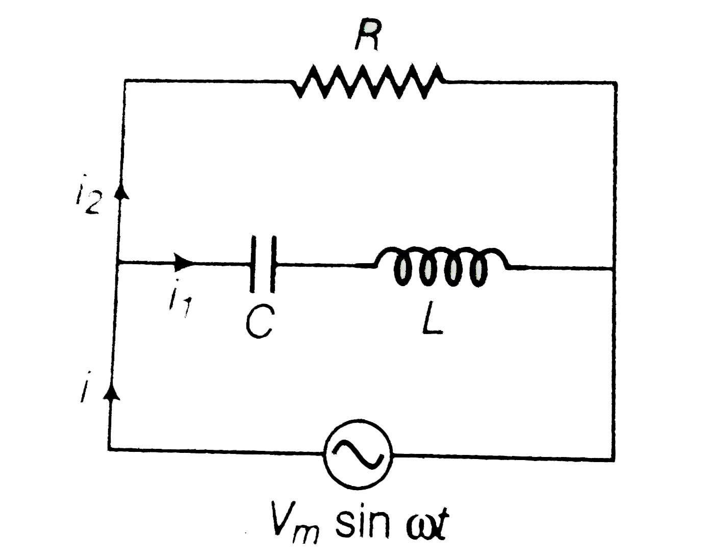
Consider the L-C-R circuit shown in the fiure. Find the net current I and the phase of i. Show that i=VZ. Find the impedance Z of this circuit.
View SolutionConsider the L-C-R circuit shown in the fiure. Find the net current I and the phase of i. Show that i=VZ. Find the impedance Z of this circuit.

View Solution
Knowledge Check
Consider the circuit shown in the figure. The current i3 is equal to
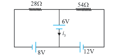 A5ampB2ampC−3ampD−5/6amp
Consider the circuit shown in the figure. The current I3 is equal to
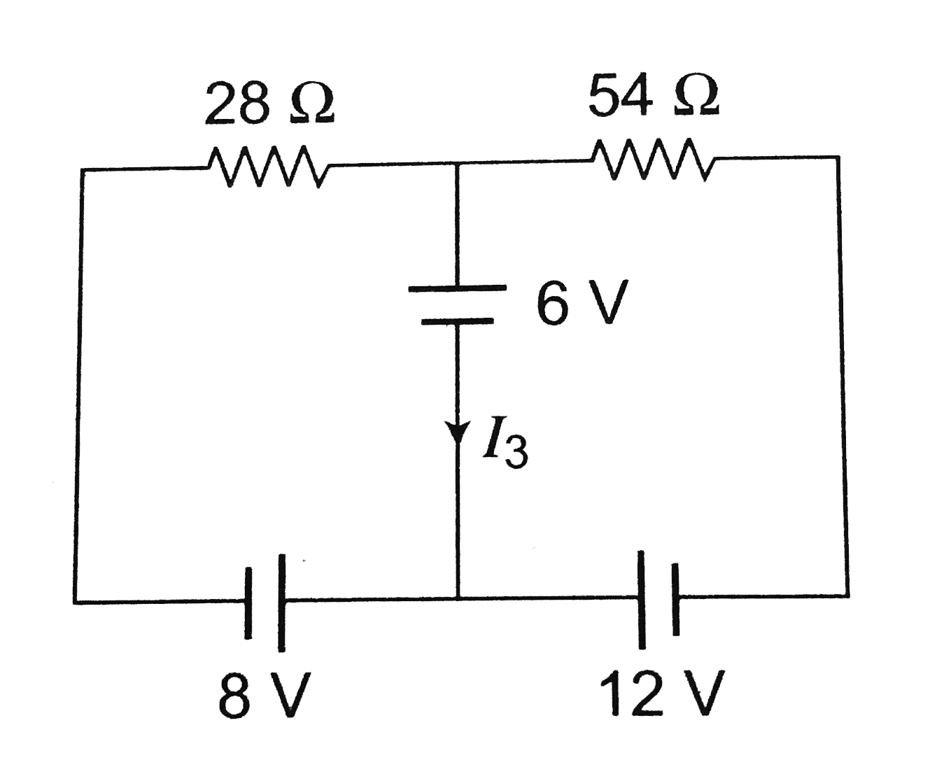 A5ampB3ampC−3ampD−5/6amp
For the circuit shown in the figure, the current I will be
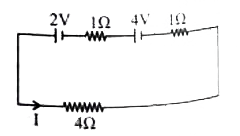 A1AB1.5AC0.5AD0.75A
Consider the LCR circuit shown in Fig. Find the net current I and the phase of i. show that i=υZ . Find the impedence Z for this circuit.
View SolutionConsider the circuit shown in the figure. The current I3 is equal to

View SolutionIn the circuit shown in the figure
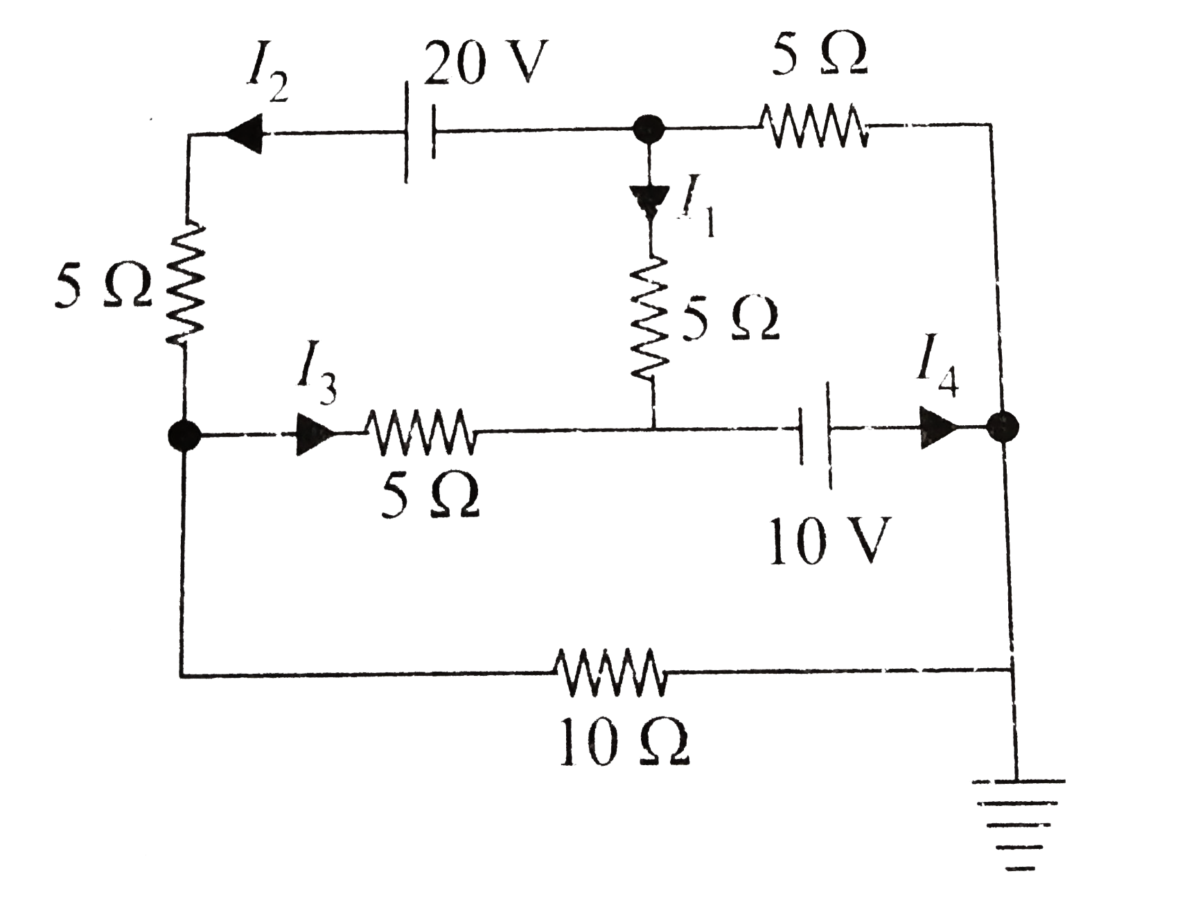 .
.
The value of current I4 is
View SolutionFind the current I in circuit
View SolutionIn the circuit shown in the figure
 .
.
The value of current I4 is
View Solution
