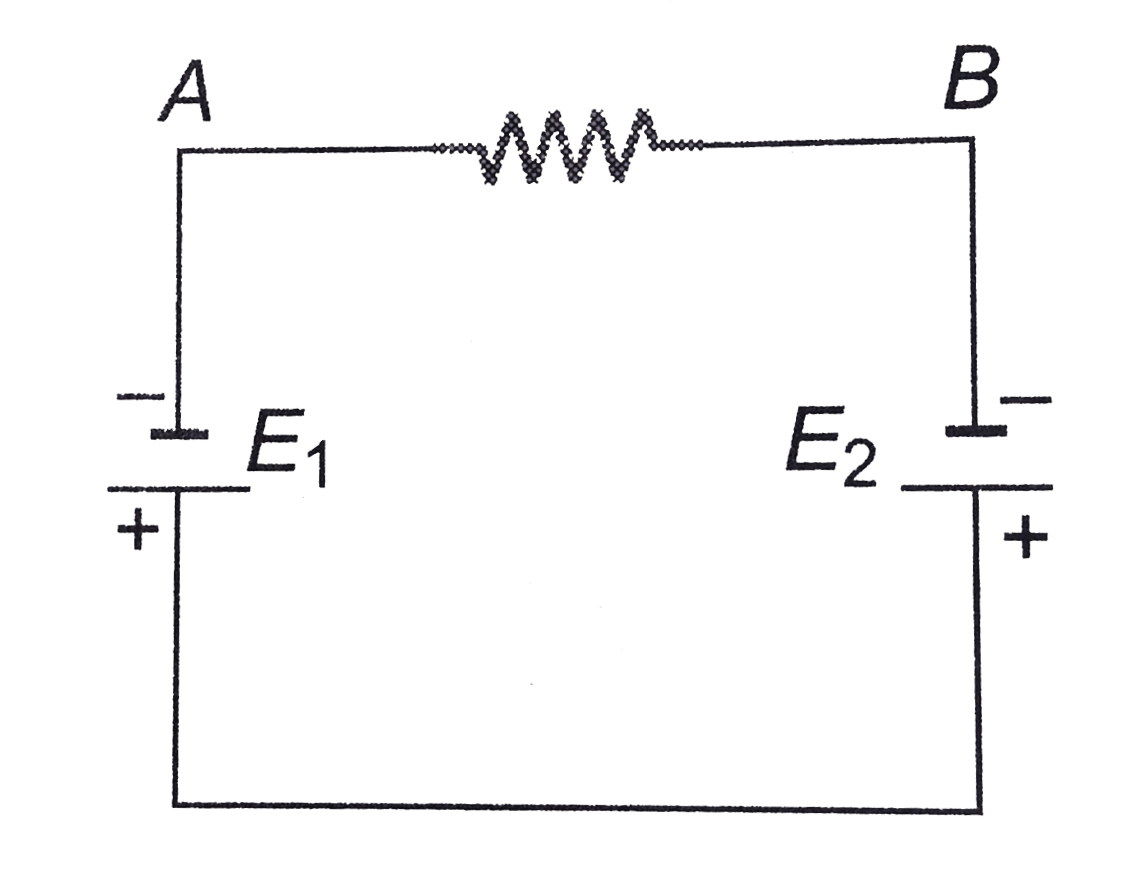
In Figure and
(a) What is the direction of the current in the resistor?
(b) Which battery is doing positive work?
(c) Which point, or , is at the higher potential?
The correct Answer is:A, B, C
a.
therefore, net curren is anti clockwise or from to.
b.current through is normal. Hence,it is doing the positive work.
c. Current flows from to
Topper's Solved these Questions
- CURRENT ELECTRICITYBOOK - DC PANDEY ENGLISHCHAPTER - CURRENT ELECTRICITYEXERCISE - Level 2 Single Correct
26 Videos
- CURRENT ELECTRICITYBOOK - DC PANDEY ENGLISHCHAPTER - CURRENT ELECTRICITYEXERCISE - Level 2 More Than One Correct
10 Videos
- CURRENT ELECTRICITYBOOK - DC PANDEY ENGLISHCHAPTER - CURRENT ELECTRICITYEXERCISE - OBJECTIVE_TYPE
1 Videos
- COMMUNICATION SYSTEMBOOK - DC PANDEY ENGLISHCHAPTER - COMMUNICATION SYSTEMEXERCISE - Subjective
11 Videos
- ELECTROMAGNETIC INDUCTIONBOOK - DC PANDEY ENGLISHCHAPTER - ELECTROMAGNETIC INDUCTIONEXERCISE - Medical entrances gallery
25 Videos
Similar Questions
In the circuit shown in figure, E=120V,R1=30.0Ω,R2=50.0Ω and L=0.200H. Switch S is closed at t=0. Just after the switch is closed.
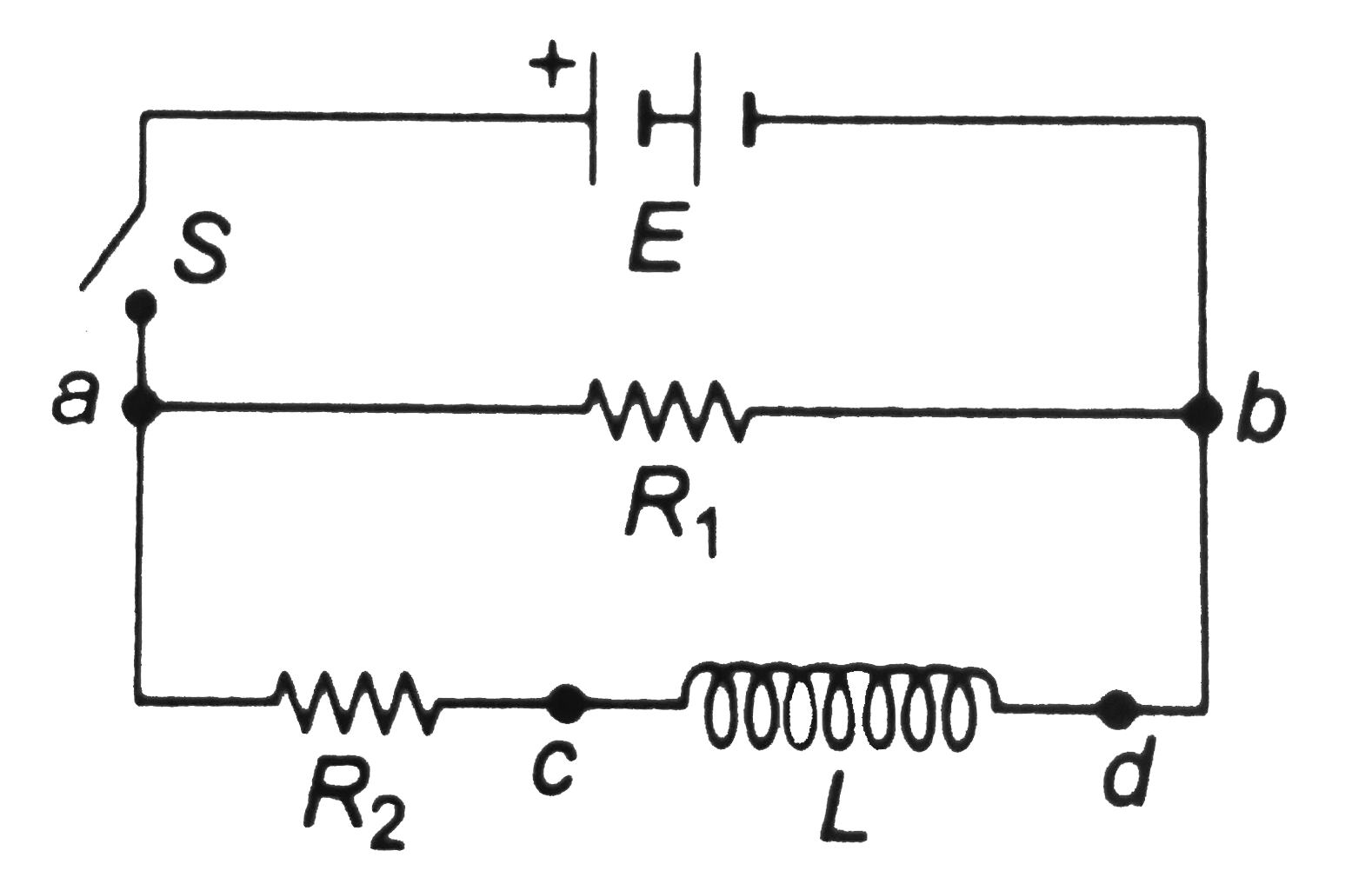
(a) What is the potential difference Vab across the inductor R1?
(b) Which point, a or b, is at higher potential?
(c) What is the potential difference Vcd across the inductor L?
(d) Which point, c or d, is at a higher potential? The switch is left closed for a long time and then is opened. Just after the switch is opened
(e) What is the potential difference Vab across the resistor R1?
(f) Which point a or b, is at a higher potential?
(g) What is the potential difference Vcd across the inductor L?
(h) Which point, c or d, is at a higher potential?
View SolutionAn ideal voltmeter V is connected to a 2.0Ω resistor and a battery with emf 5.0V and internal resistance 0.5Ω as shown in figure
(a) What is the current in the 2.0Ω resistor?
(b) What is the terminal voltage of the battery?
(c) What is the reading of the voltmeter?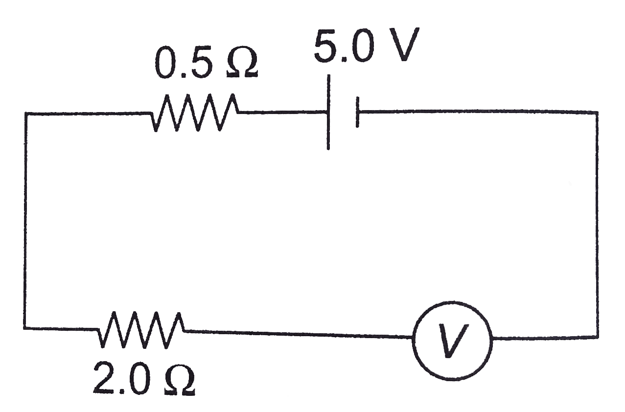
View SolutionIn the circuit given in the figure, both batteries are ideal . Emf E1 of battery 1 has a fixed value, but emf E2 of battery 2 can be varied between 1.0Vand10.0V . The graph gives the currents through the two batteries as a function of E2 but are not marked as which plot corresponds to which battery. But for both plots, current is assumed to be negative when the direction of the current through the battery is opposite to the direction of that battery's emf (direction of emf is from negative to positive.)
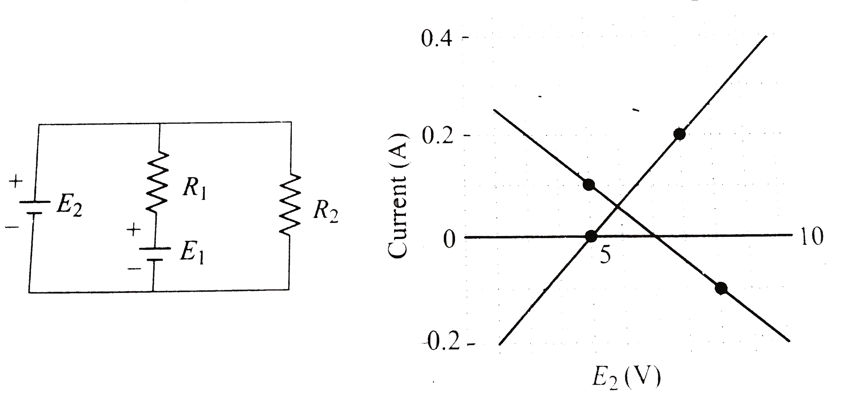
The value of emf E1 is
View SolutionIn the circuit given in the figure, both batteries are ideal . Emf E1 of battery 1 has a fixed value, but emf E2 of battery 2 can be varied between 1.0Vand10.0V . The graph gives the currents through the two batteries as a function of E2 but are not marked as which plot corresponds to which battery. But for both plots, current is assumed to be negative when the direction of the current through the battery is opposite to the direction of that battery's emf (direction of emf is from negative to positive.)
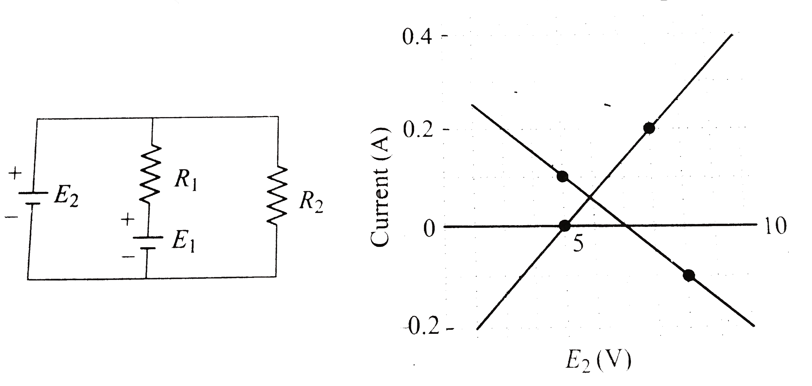 ,
,
The resistance R1 has value
View SolutionIn the circuit given in the figure, both batteries are ideal . Emf E1 of battery 1 has a fixed value, but emf E2 of battery 2 can be varied between 1.0Vand10.0V . The graph gives the currents through the two batteries as a function of E2 but are not marked as which plot corresponds to which battery. But for both plots, current is assumed to be negative when the direction of the current through the battery is opposite to the direction of that battery's emf (direction of emf is from negative to positive.)
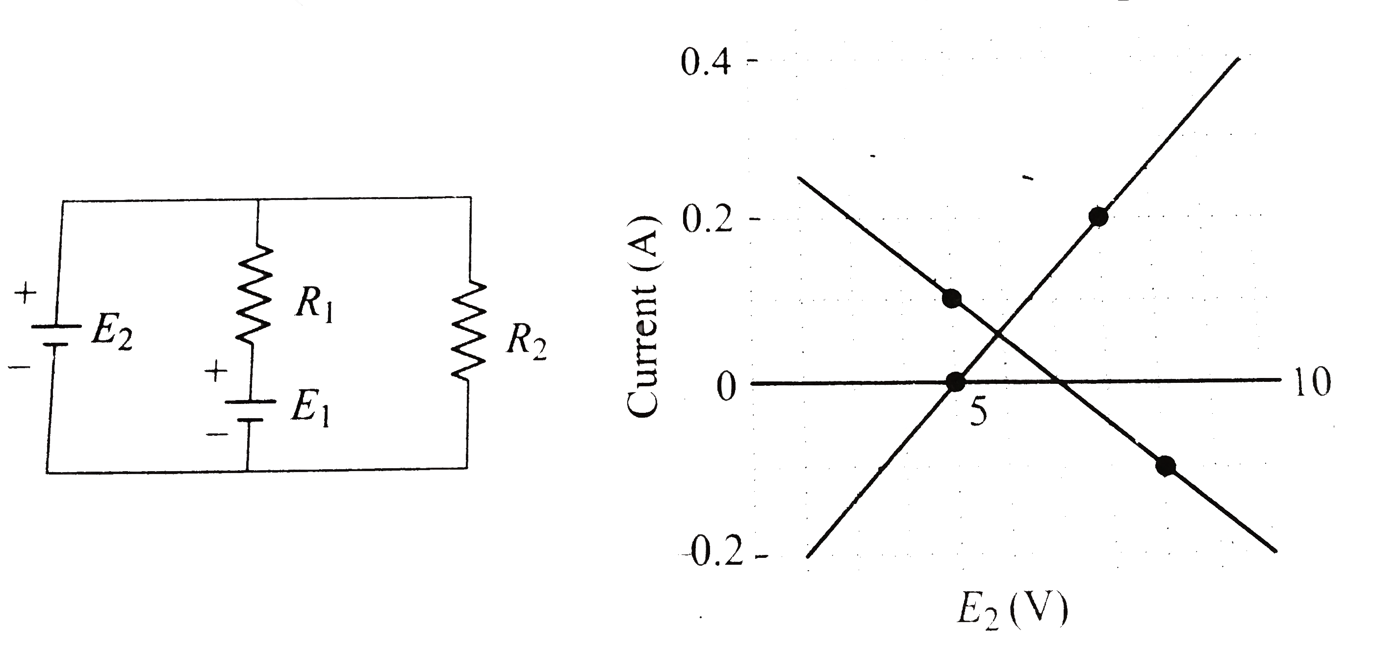 ,
,
The resistance R2 is equal to
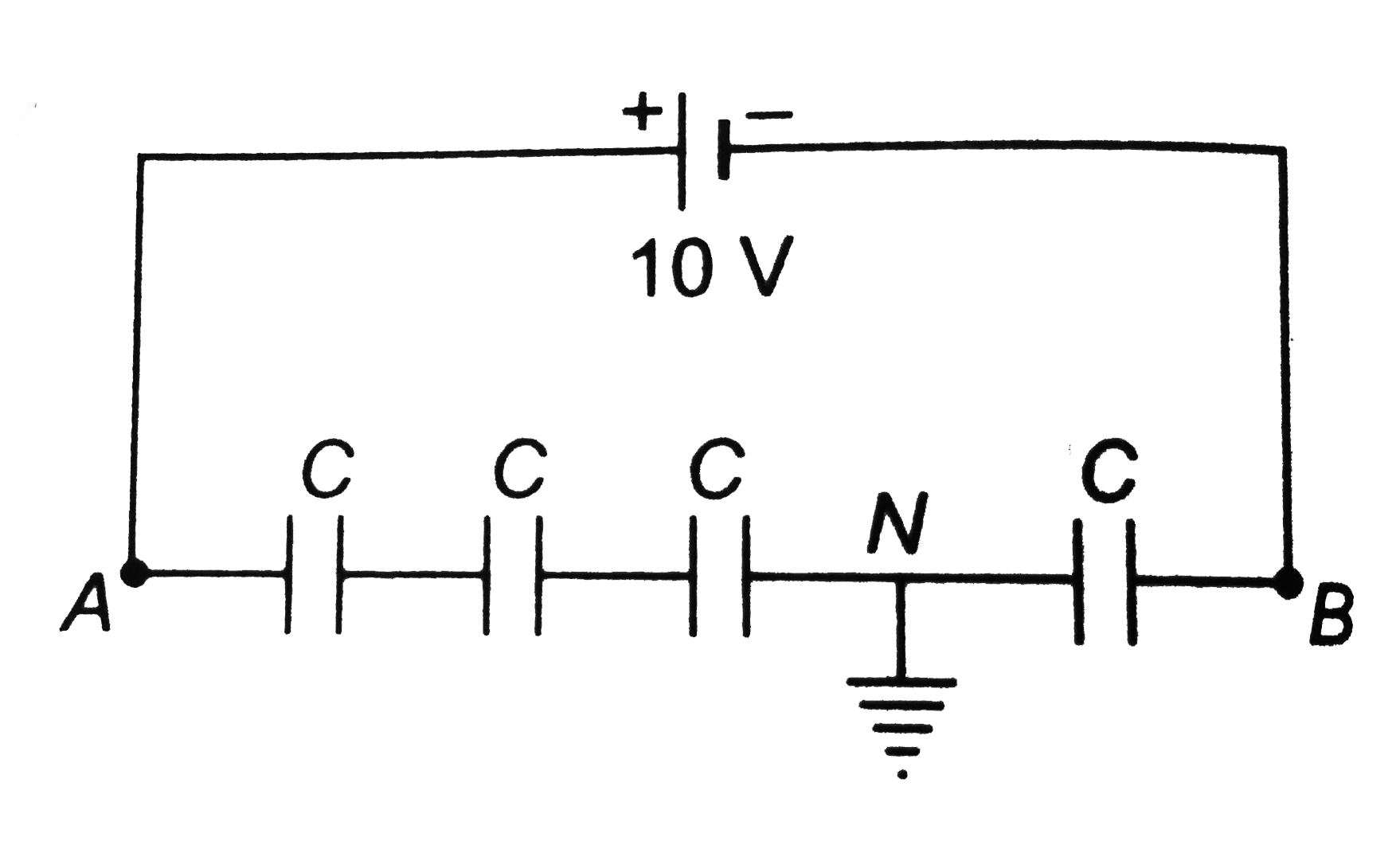
View SolutionFour identical capacitors are connected in series with a 10V battery as shown in the figure. The point N is earthed. The potentials of points A and B are
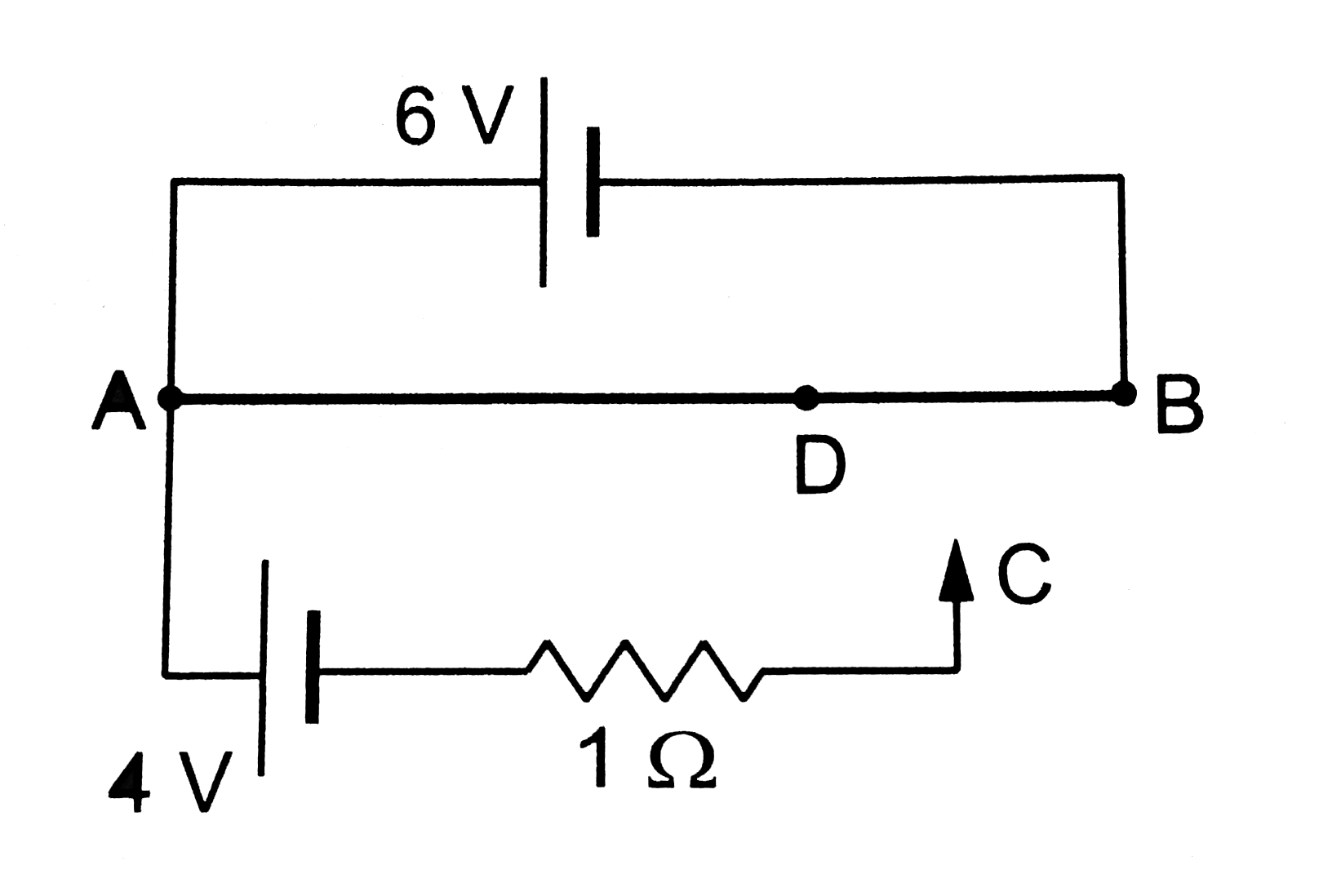
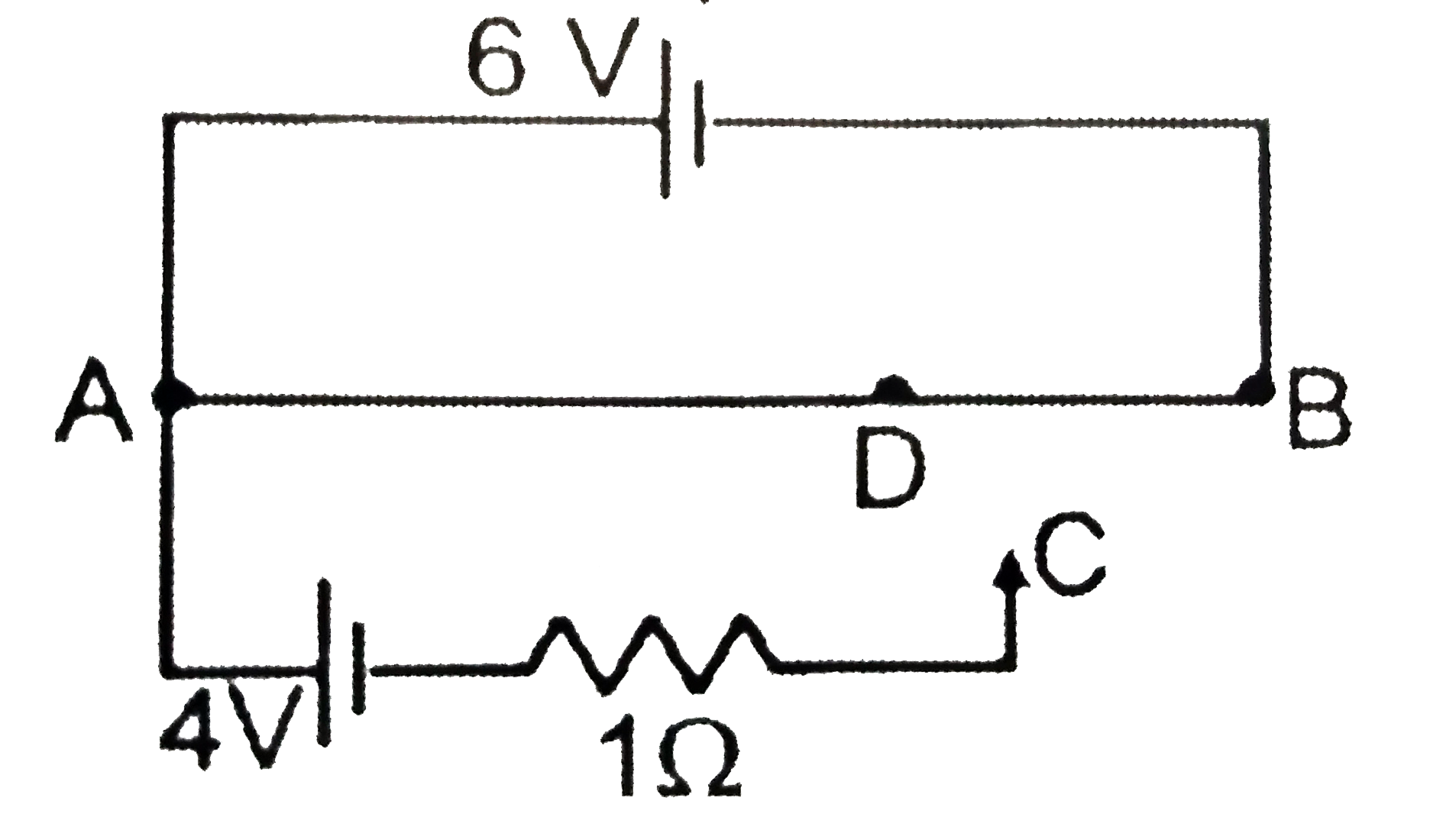
View SolutionA 6-volt battery of negligible internal resistance is connected across a uniform wire AB of length 100cm. The positive terminal of another battery of emf 4V and internal resistance 1(Ω)is joined to the point A as shown in figure.Take the potential at B to be zero. (a) What are the potentials at the poits A and C ? (b) At which point D of the wire AB, the potential is equal to the potential at C?(c ) If the point C and D are connected by a wire, what will be the current through it ? (d) If the 4V battery is replaced by 7.5V battery,wht would be the answer of parts (a) and (b) ?
View SolutionA 2V battery is connected across AB as shown in the figure. The value of the current supplied by the battery when in one case battery's positive terminal is connected to A and in other case when positive terminal of battery is connected to B will respectively be :-
_E01_501_Q01.png)
View SolutionA 6 volt battery of negligible internal resistance is connected across a uniform wire AB of length 100cm. The positive terminal of another battery of emf 4V and internal resistance 1Ω is joind to the point A as shown in figure. Take the potential at B to be zero. (a) What are the potentials at the points A and C ? (b) At which D of the wire AB, the potential is equal to the potential at C. ( c) If the point C and D are connected by a wire. What will be the current through is ? (d) Id the 4V batteryt is replaced by 7.5 V battery, what whould be the answers of parts (a) and (b) ?
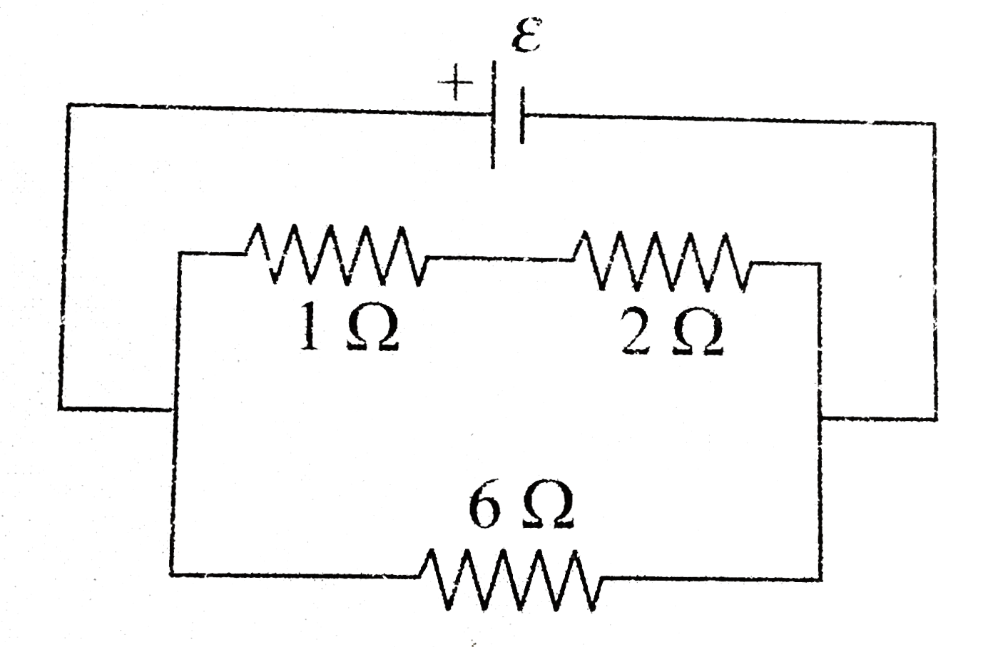
View SolutionIn the circuit shown in fig the voltage across the 2 Ω resistor is 12V. What is the emf of the battery and the current thorugh the 6 Ω resistor?
View Solution
