In the circuit shown in figure E1,E2=20V,R1=R2=10kΩ and C=1μF. Find the current through R1,R2 and C when
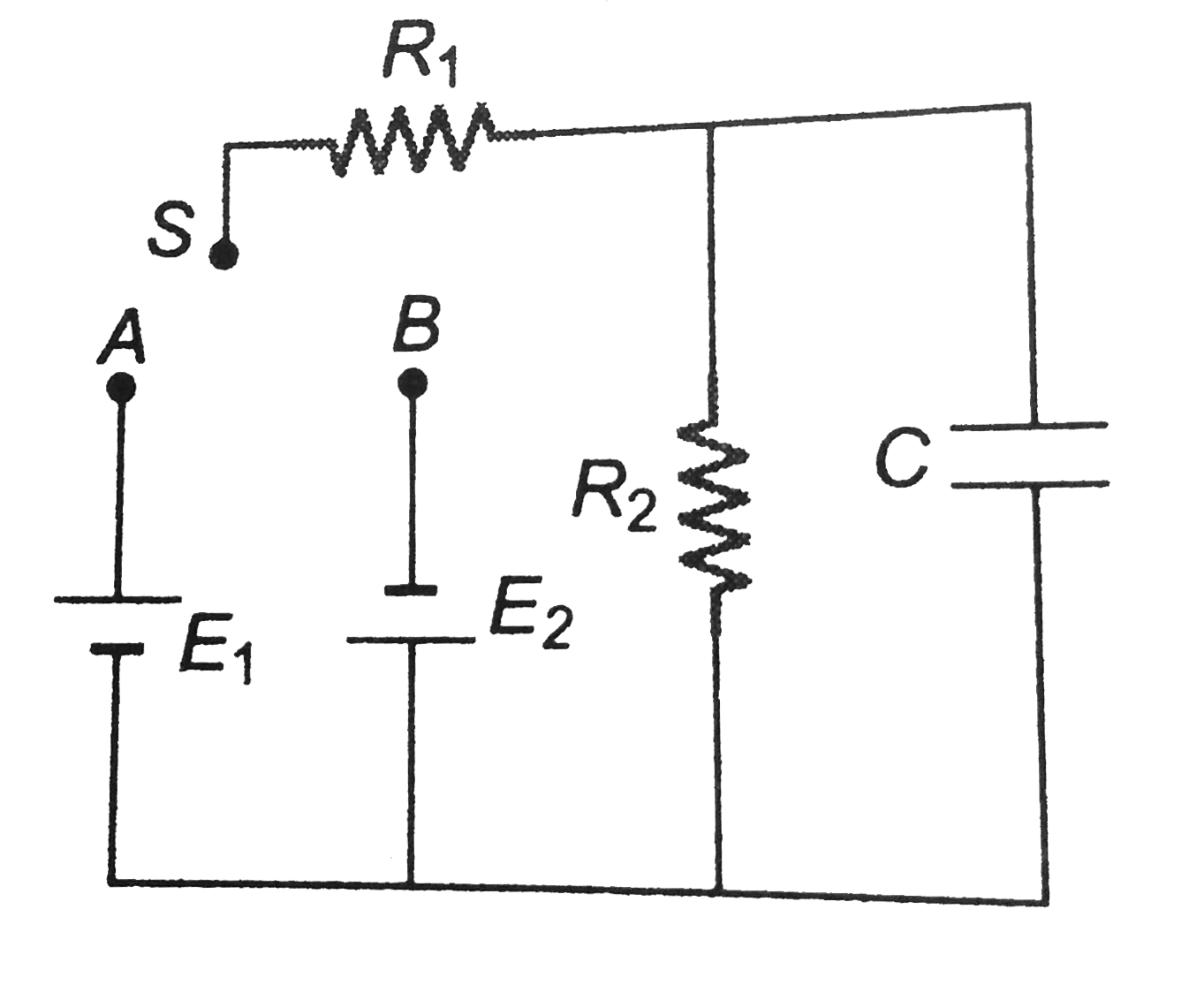
(a) S has been kept connected to A for a long time.
(b) The switch is suddenly shifted to B.
The correct Answer is:A, C
a. After long time, capacitor gets fully charged by E1
∴iC=0
and iR1=iR2=E1R1+R2
=2020×103
=10−3A=1mA
b. in steady state (with E1).
VC=VR2=VR1
=E12=10V
Now when the switch is shifted to position B, capcitor (at t=0) behaves like a battery of 10 V.
The circuit in that case is as shown below.
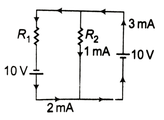
Now, with the help of Kirchoff's laws we can find different currents., final currents are shown in the figure.
Topper's Solved these Questions
- CAPACITORSBOOK - DC PANDEY ENGLISHCHAPTER - CAPACITORSEXERCISE - OBJECTIVE_TYPE
1 Videos
- CAPACITORSBOOK - DC PANDEY ENGLISHCHAPTER - CAPACITORSEXERCISE - OBJECTIVE_TYPE
1 Videos
- ATOMSBOOK - DC PANDEY ENGLISHCHAPTER - ATOMSEXERCISE - MEDICAL ENTRANCES GALLERY
42 Videos
- COMMUNICATION SYSTEMBOOK - DC PANDEY ENGLISHCHAPTER - COMMUNICATION SYSTEMEXERCISE - Subjective
11 Videos
Similar Questions
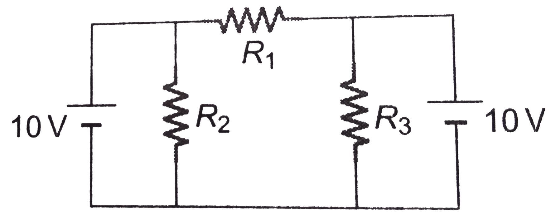
In the curcuit shown in figure R1=R2=R3=10Ω. Find the currents through R1 and R2
View SolutionIn the circuit shown in figure
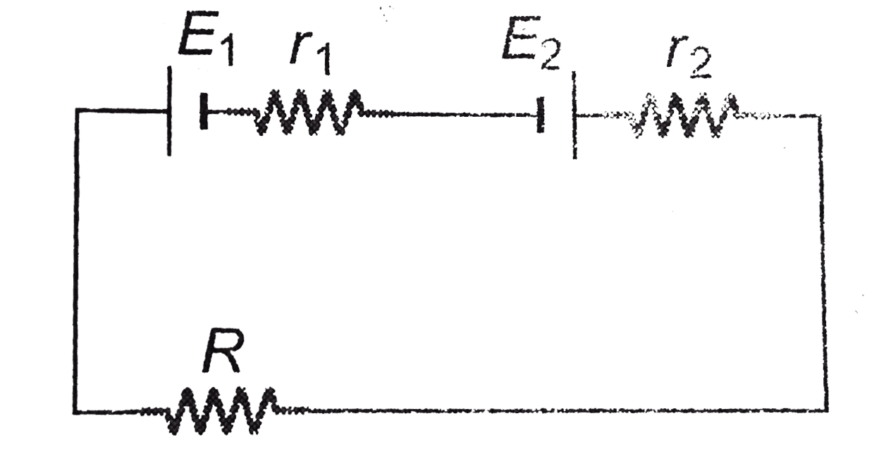
E1=10V,E2=4V,r1=r2=1Ω and R=2Ω.
Find the potential difference across battery 1 and battery 2.
View SolutionIn the circuit shown in figure

E1=10V,E2=4V,r1=r2=1Ω and R=2Ω.
Find the potential difference across battery 1 and battery 2.
View SolutionIn the circuit shown in figure E1=7V,E2=1V,R1=2Ω,R2=2Ω and R3=3Ω respectively. Find the power supplied by the two batteries.
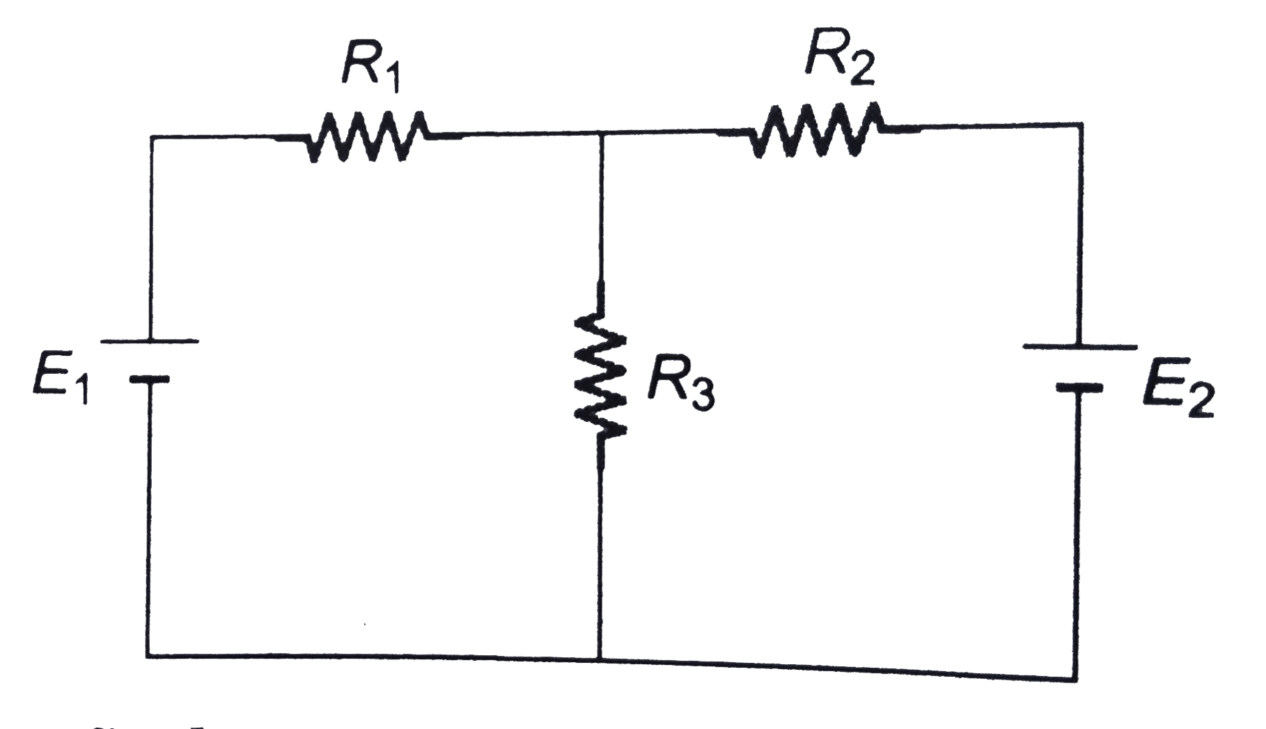
View SolutionIn the circuit shown, E1=7V,E2=7V,R1=R2=1Ω and R3=3Ω respectively. The current through the resistance R3
View SolutionIn the circuit shown, E1=7V,E2=7V,R1=R2=1Ω and R3=3Ω respectively. The current through the resistance R3

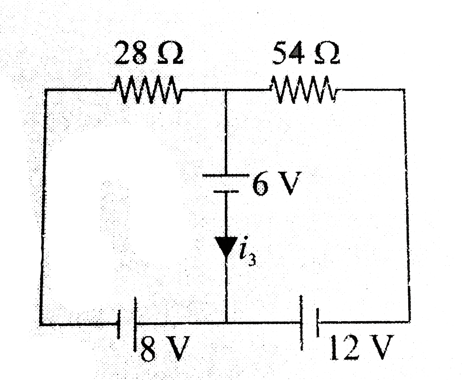
View SolutionIn the following circuit ,E1=4V,R1=2Ω,
E2=6V,R2=2Ω,andR3=4Ω. Find the currents i1andi2
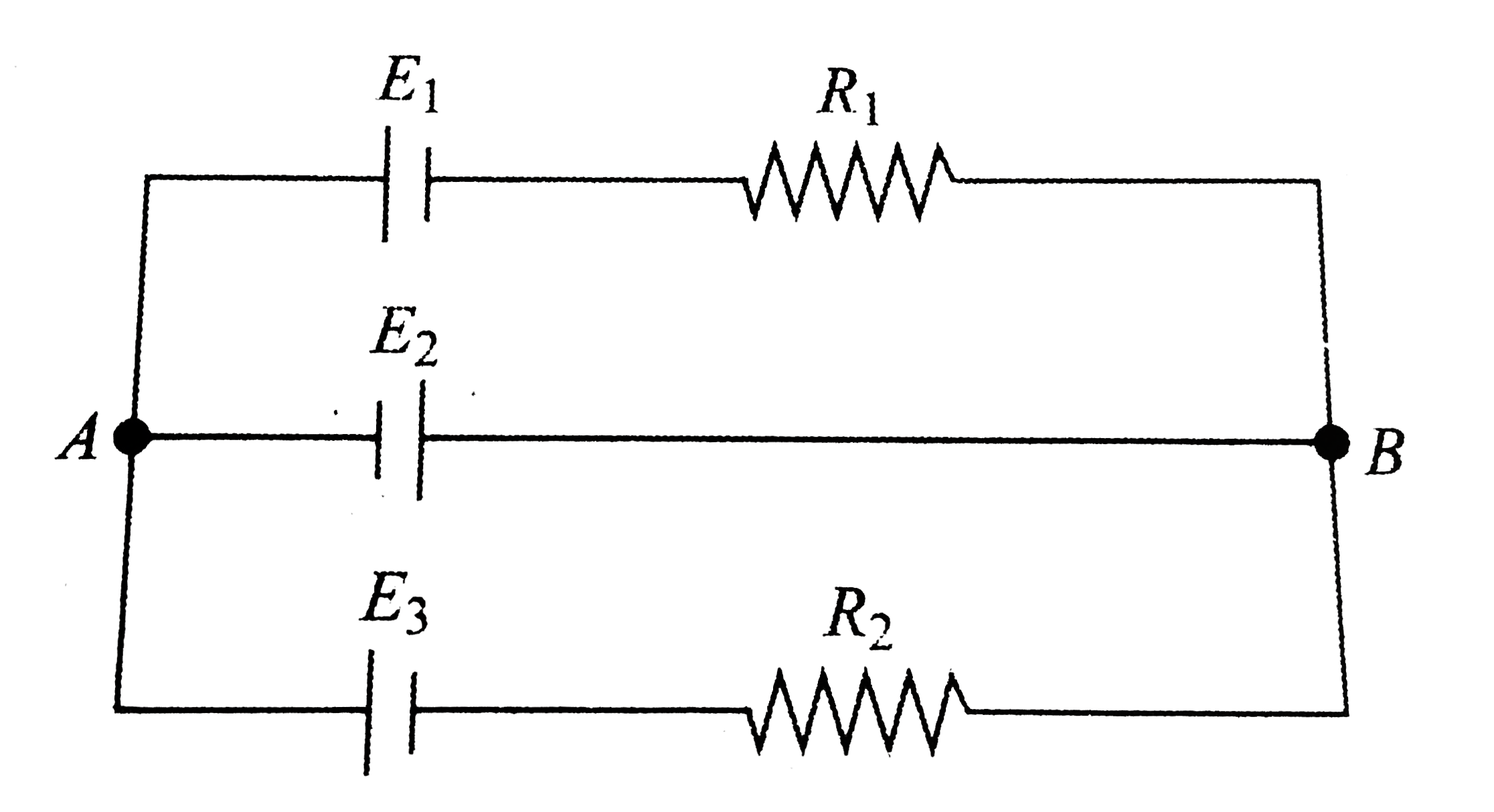
View SolutionIn the circuit shown in fig. 5.265, E1=E2=E3=2V and R1=R2=4Ω. The current flowing between points A and B through battery E2 is
View Solution

In the circuit shown in figure. ε1=3,ε2=2,ε3=6V,R1=2,R4=6Ω,R3=2,R2=4ΩandC=5μF. Find the current in the resistor R3 and the electrical energy stored in the capacitor C.
View SolutionIn the circuit in figure E1=3V,E2=2V,E3=1V and R=r1=r2=r3=1Ω
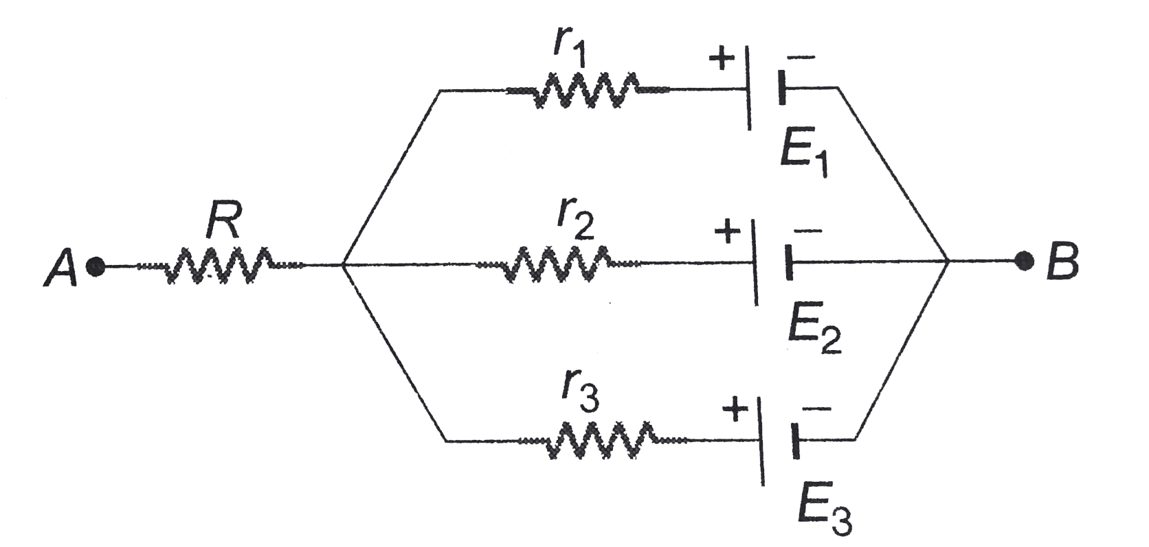
Find the potential differece between the points A and B and the currents through each branch.
View Solution
