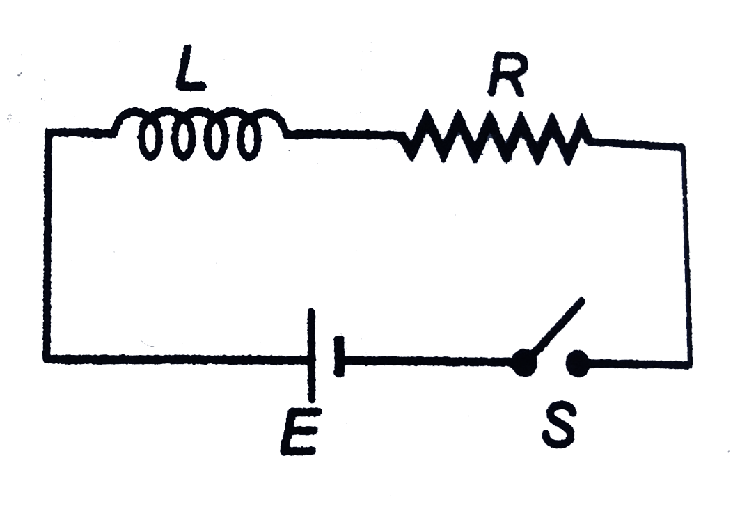
In the circuit shown in figure L=10H,R=5Ω,E=15V. The switch S is closed at t=0. At t=2s the current in the circuit is
3(1−1e)A
3(1−1e2)A
3(1e)A
3(1e2)A
The correct Answer is:A
τL=LR=2s
i0=ER=3A,t=2s
i=i0(1−e−t/τL)
Substituting the given values, we can find i.
Topper's Solved these Questions
- BOOK - DC PANDEY ENGLISHCHAPTER - ELECTROMAGNETIC INDUCTIONEXERCISE - Objective Questions3videos
ELECTROMAGNETIC INDUCTION
- BOOK - DC PANDEY ENGLISHCHAPTER - ELECTROMAGNETIC INDUCTIONEXERCISE - Level 1 Subjective21videos
ELECTROMAGNETIC INDUCTION
- BOOK - DC PANDEY ENGLISHCHAPTER - ELECTROMAGNETIC INDUCTIONEXERCISE - Level 1 Assertion And Reason10videos
ELECTROMAGNETIC INDUCTION
- BOOK - DC PANDEY ENGLISHCHAPTER - CURRENT ELECTRICITYEXERCISE - Medical entrances gallery97videos
CURRENT ELECTRICITY
- BOOK - DC PANDEY ENGLISHCHAPTER - ELECTROMAGNETIC WAVESEXERCISE - Sec C22videos
ELECTROMAGNETIC WAVES
Similar Questions
Switch is closed at t=0 then the current in the circuit at t=L2R is
_PHY_E06_157_Q01.png) View Solution
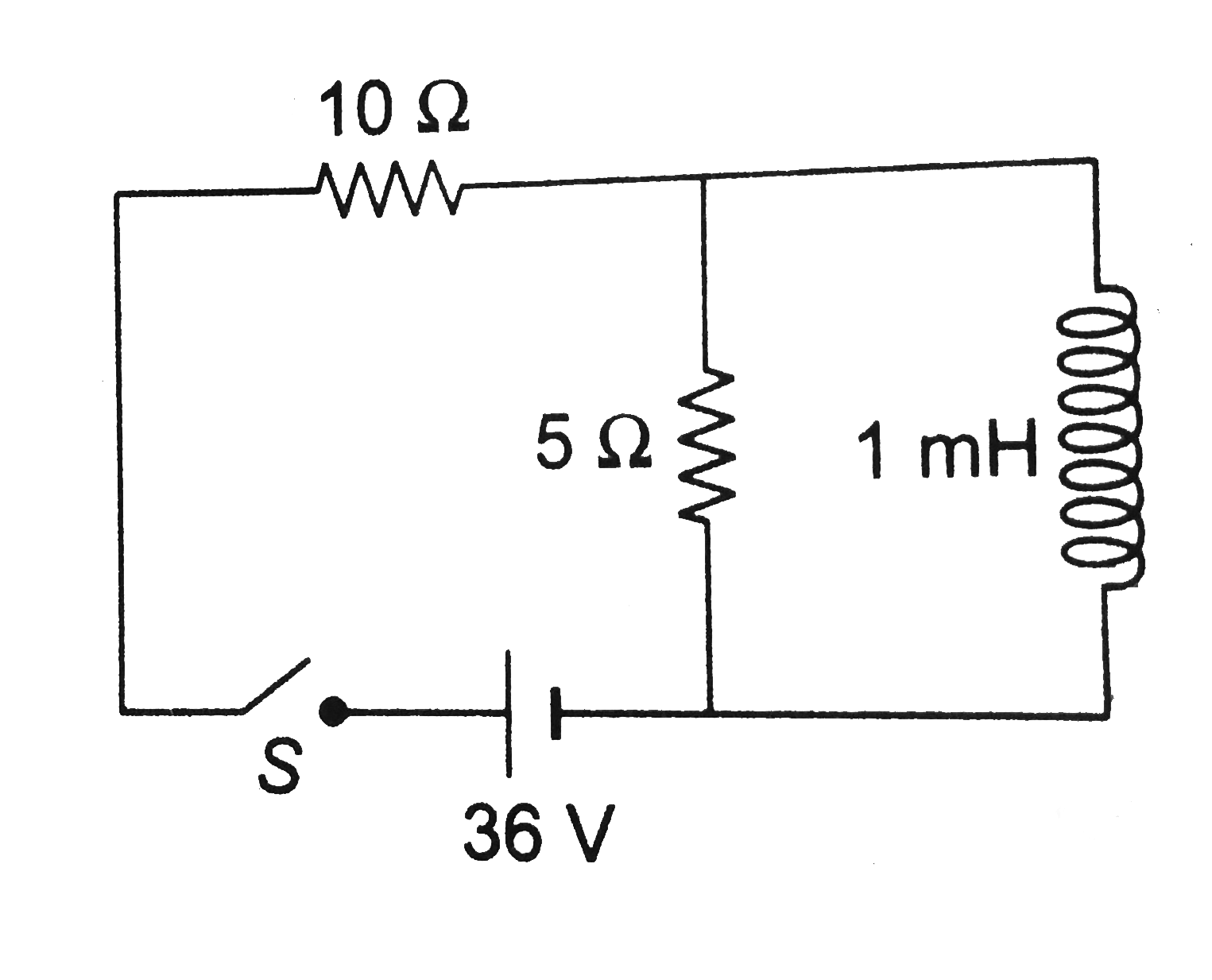
View SolutionIn the circuit arrangement shown in figure, the switch S is closed at t=0. Find the current in the inductance as a function of time? Does the current through 10Ω resistor vary with time or remains constant.
 View Solution
In the circuit shown in figure the switch S is closed at t = 0. A long time after closing the switch
 View Solution
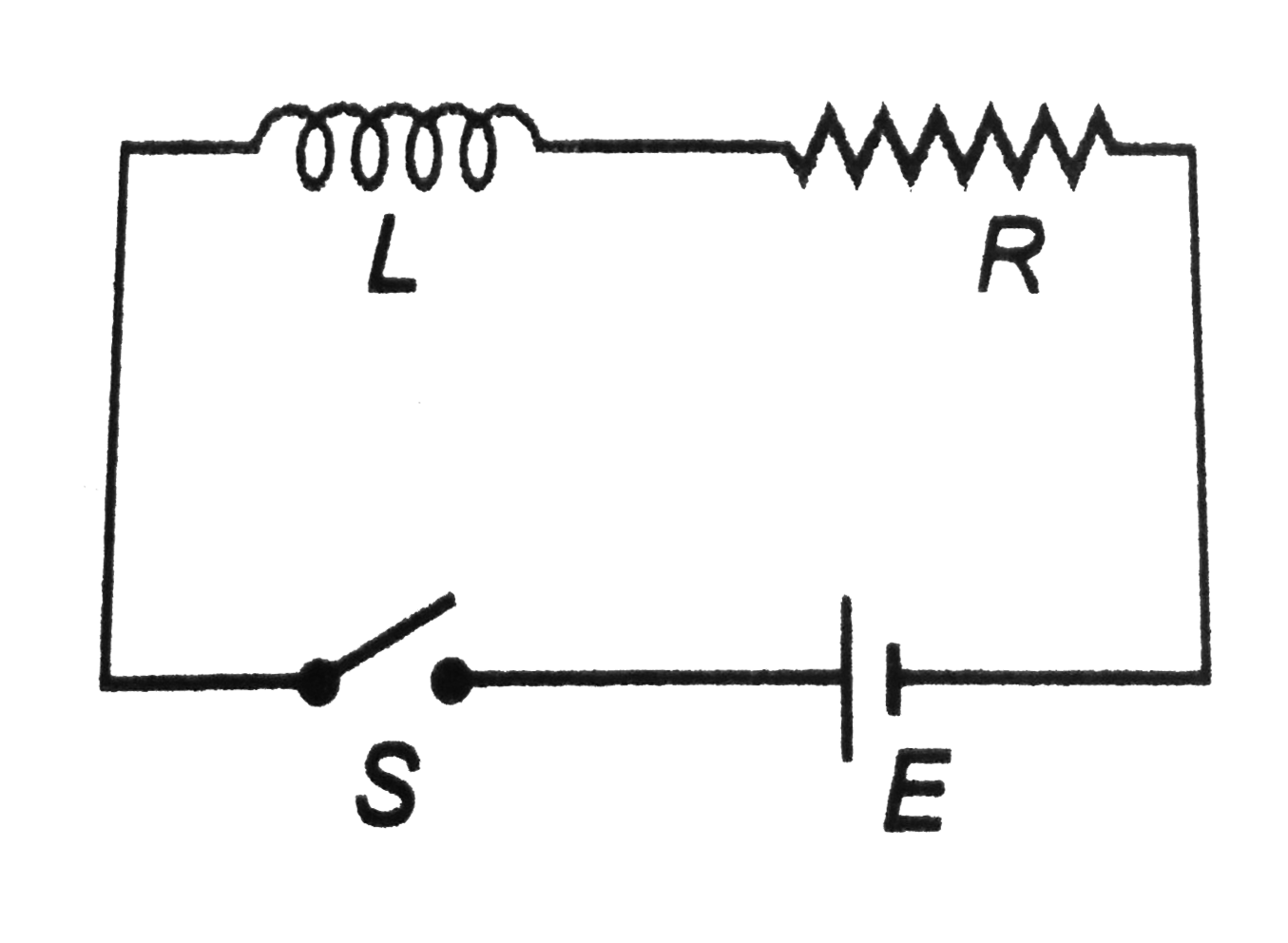
In the circuit shown in figure, the switch S is closed at t=0. If VL is the voltge induced across the inductor and i is the instantaneous current, the correct variation of VL versus is given by
 View Solution
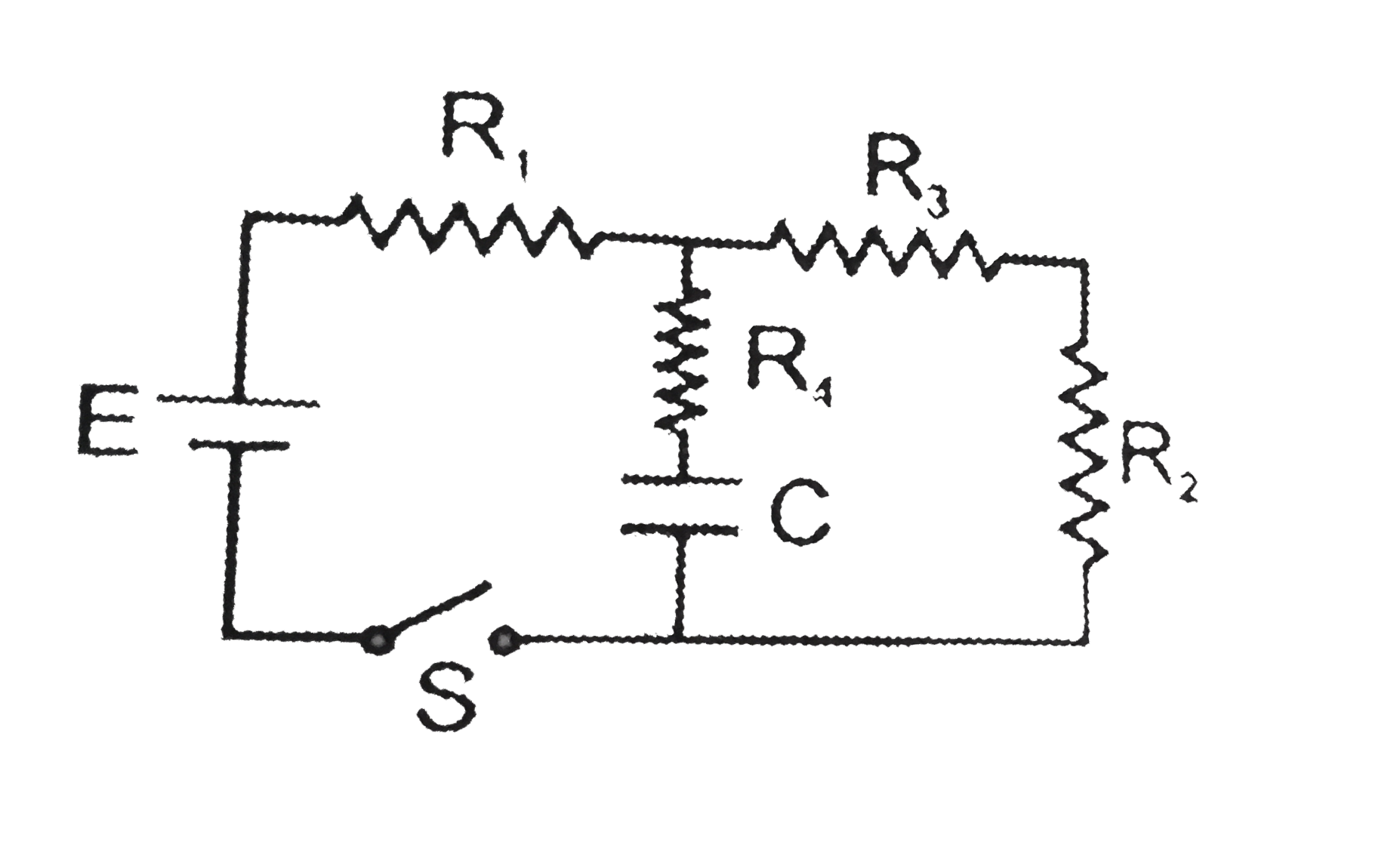
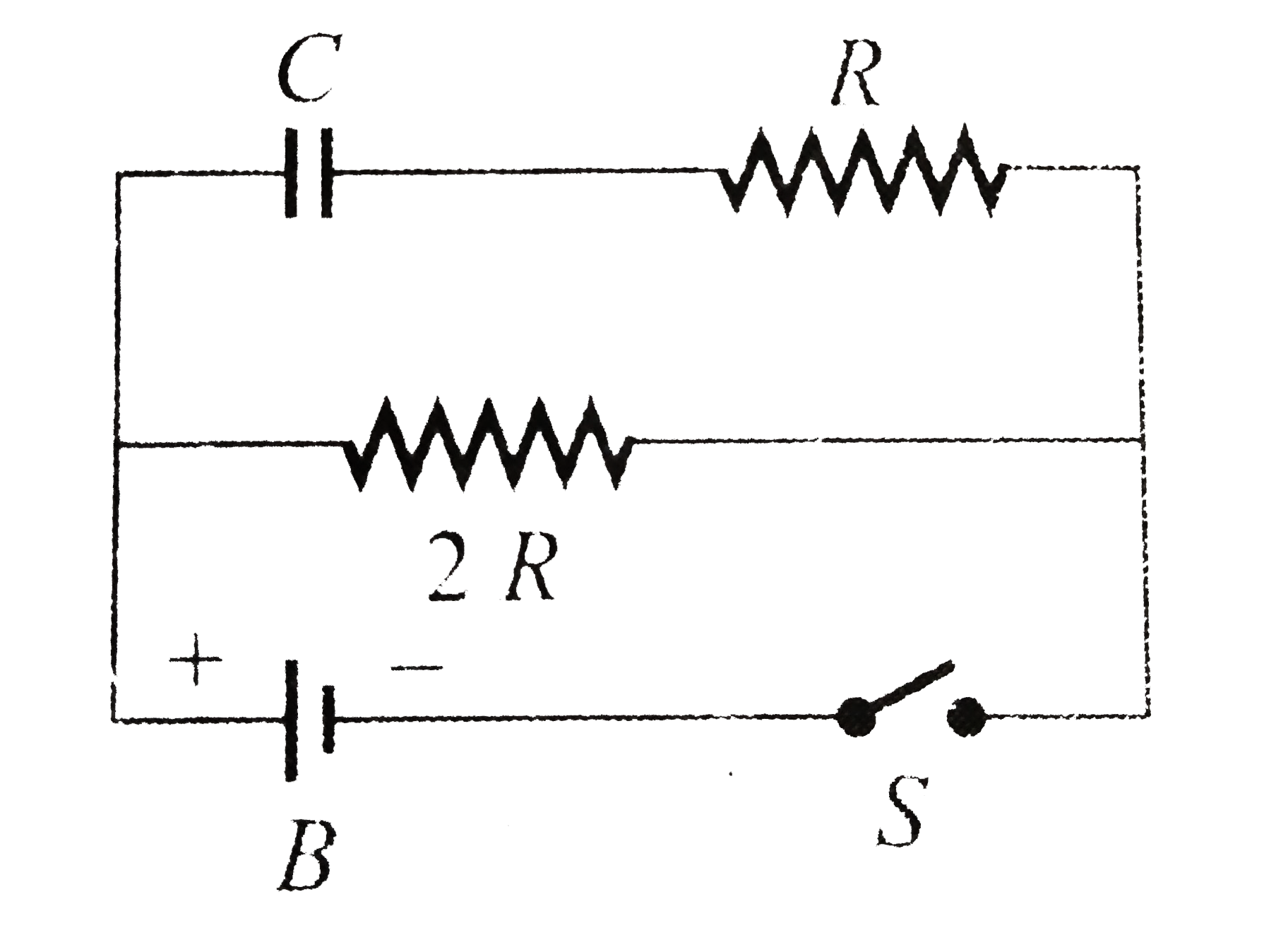
In the circuit shown in fig, if the switch S is closed at t=0 , the capacitor charges with a time constant
 View Solution
In the circuit shown in figure switch S is closed at time t=0
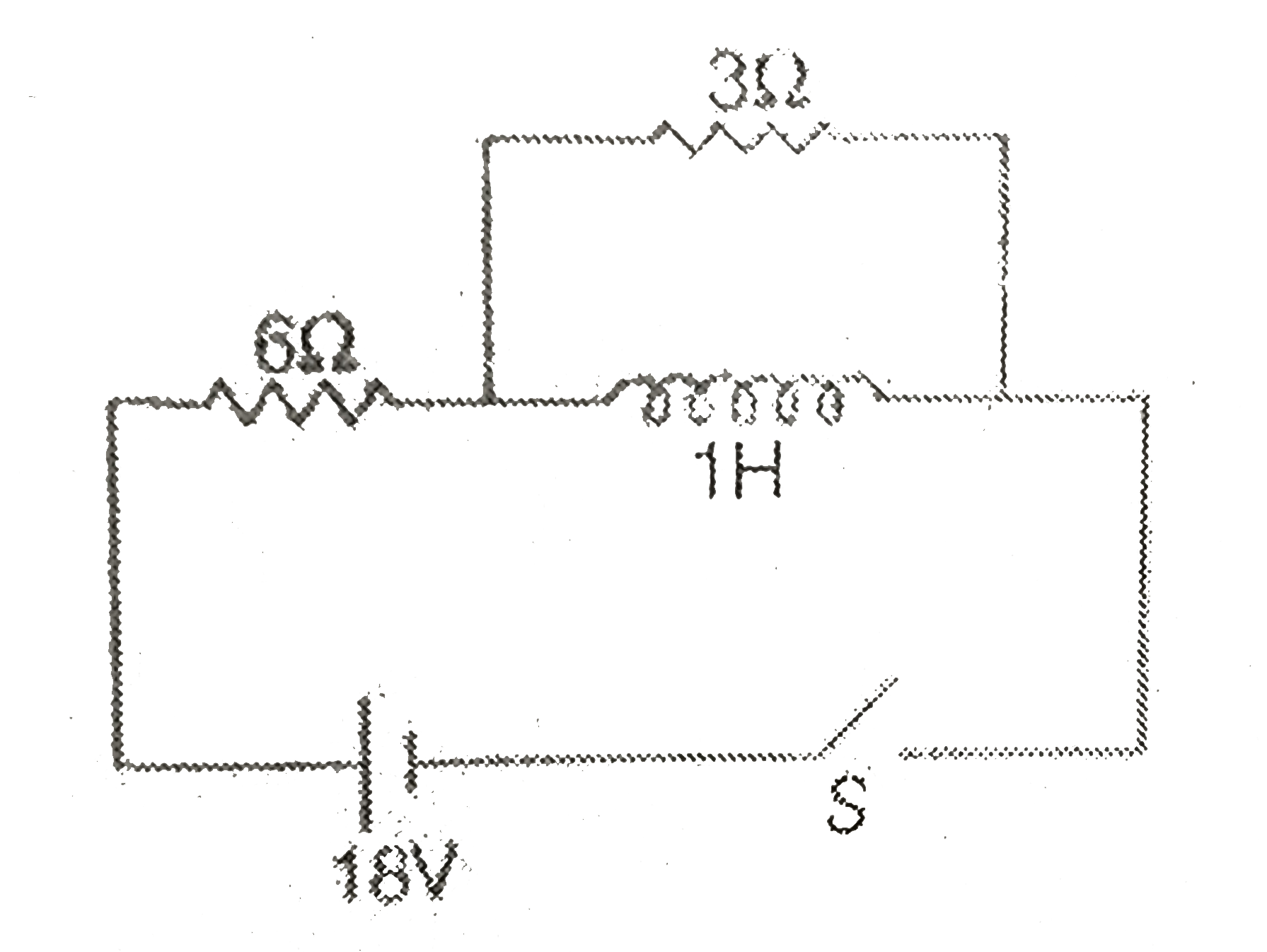
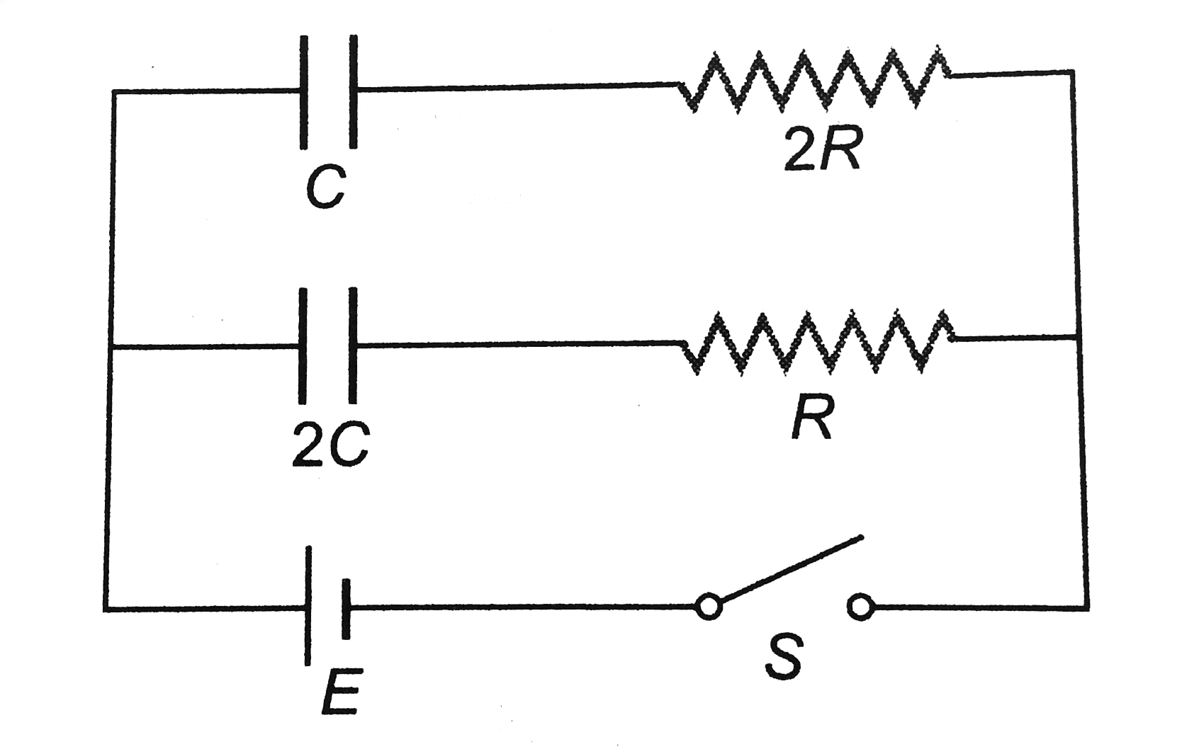
At what time current through 3Ω resistance and 1H inductor are equal?View SolutionIn the circuit shown in the figure, switch S is closed at time t=0. Select the correct statements.
 View Solution
In the circuit shown in the figure, switch S is closed at time t=0. Select the correct statements.
 View Solution
In the circuit shown in figure switch S is closed at time t=0
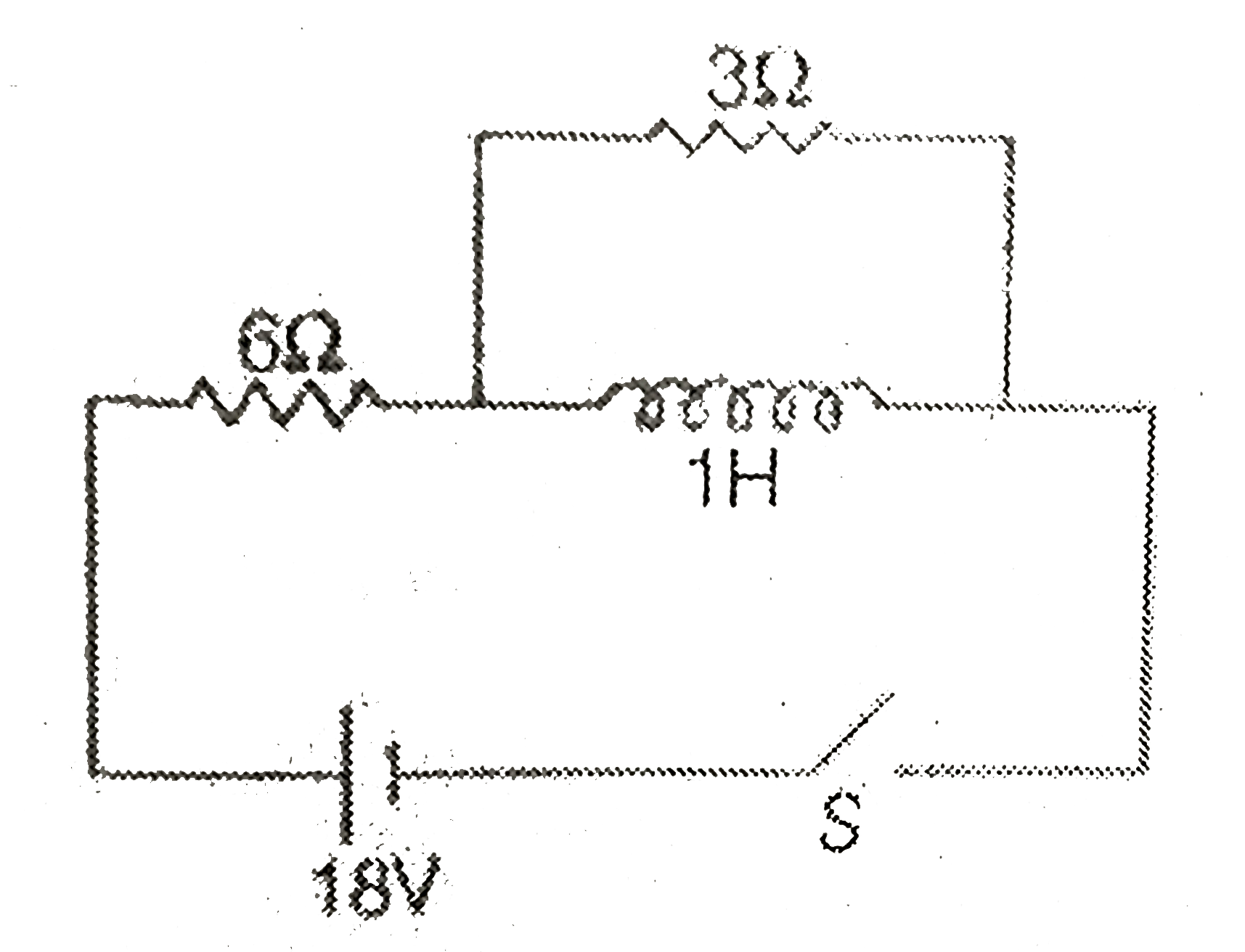
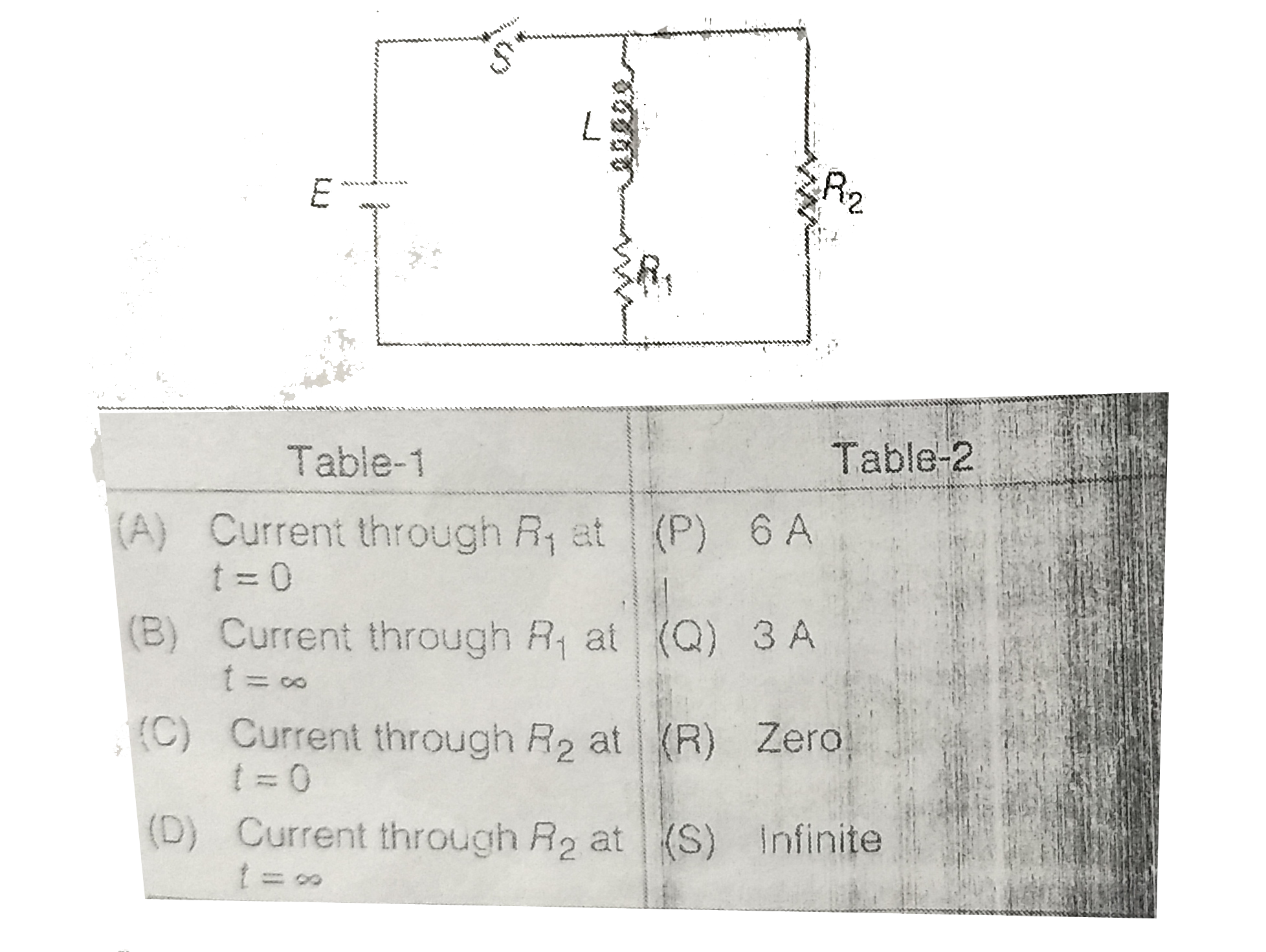
Takin left to right current through the indcutor as apositive current, current through inductor varies with time asView SolutionIn the circuit diagram shown in Figure E=18V , L=2H, R1=3Ω,R2=6Ω. Switch S is closed at t=0 Match the following:
 View Solution

