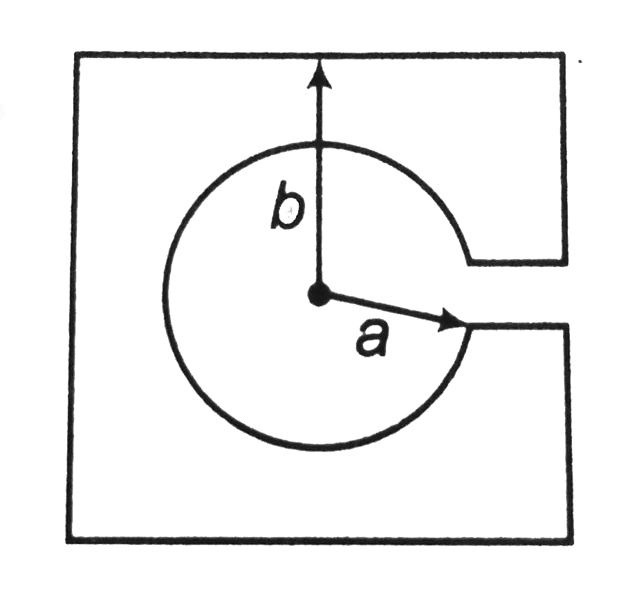
A loop shown in the figure is immersed in the varying magnetic field B=B0t, directed into the page. If the total resistance of the loop is R, then the direction and magnitude of induced current in the inner circle is
clockwise B0(πa2−b2)R
anticlockwise B0π(a2+b2)R
clockwise B0(πa2+4b2)R
clockwiseB0(4b2−πa2)R
The correct Answer is:D
|e|=dϕdt=SdBdt=(4b2−πa2)B0
i=|e|R=(4b2−πa2)B0R
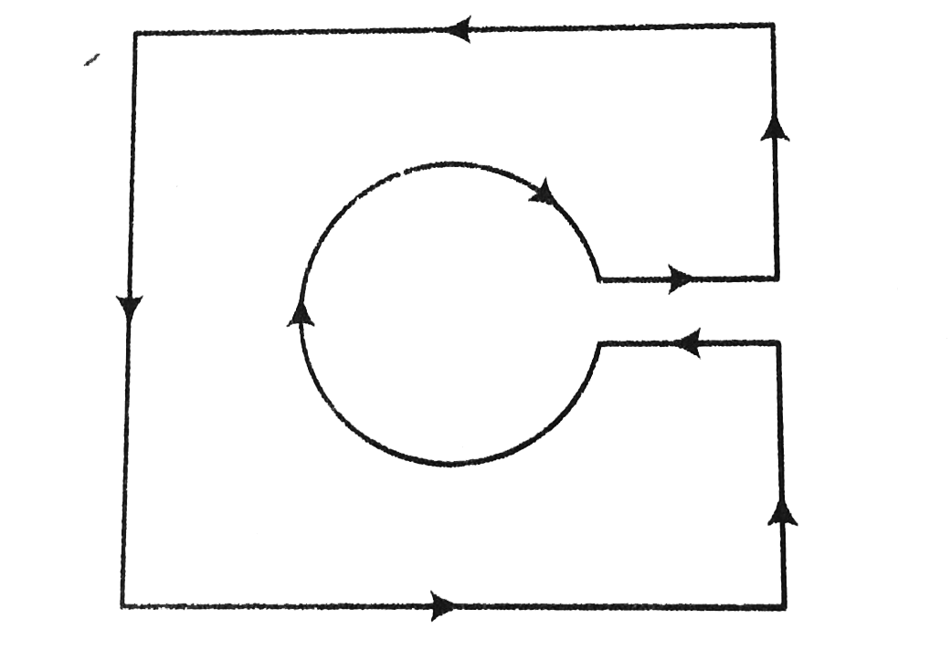
⊗ magnetic field is increasing. So, ⊙ magnetic field is produced.
Topper's Solved these Questions
- BOOK - DC PANDEY ENGLISHCHAPTER - ELECTROMAGNETIC INDUCTIONEXERCISE - Level 2 More Than One Correct10videos
ELECTROMAGNETIC INDUCTION
- BOOK - DC PANDEY ENGLISHCHAPTER - ELECTROMAGNETIC INDUCTIONEXERCISE - Level 2 Comprehension Based13videos
ELECTROMAGNETIC INDUCTION
- BOOK - DC PANDEY ENGLISHCHAPTER - ELECTROMAGNETIC INDUCTIONEXERCISE - Level 1 Subjective21videos
ELECTROMAGNETIC INDUCTION
- BOOK - DC PANDEY ENGLISHCHAPTER - CURRENT ELECTRICITYEXERCISE - Medical entrances gallery97videos
CURRENT ELECTRICITY
- BOOK - DC PANDEY ENGLISHCHAPTER - ELECTROMAGNETIC WAVESEXERCISE - Sec C22videos
ELECTROMAGNETIC WAVES
Similar Questions
A wire is bent in the form of a square of side .a. in a varying magnetic field →B='α'B0tˆk . If the resistance per unit length is λ , then find the following.
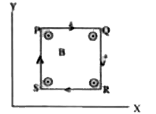
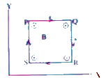
(i) The direction of induced current (ii) The current in the loop (iii) Potential difference between P and QView SolutionA wire is bent in the form of a square of side la in a varying magnetic field B=∝B0tˆk. If the resistance per unit length is λ. then find the following:
(i) The direction of induced current
(ii) The current in the loop
(iii) Potential difference between P and Q
 View Solution
Find the equivalent resistance between A and B.
 View Solution
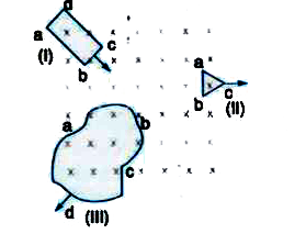
Figure shows planar loops of different shapes moving out of or into a region of a magnetic field which is directed normal to the plane of the loop away from the reader. Determine the direction of induced current in each loop using Lenz's law.
 View Solution
Current in a long current carrying wire is I=2t
A conducting loop is placed to the right of this wire. Find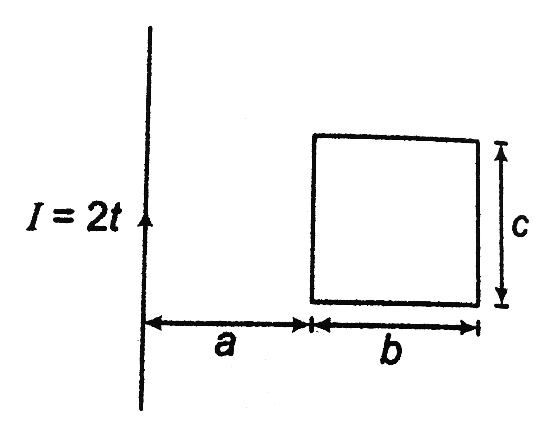
a. magnetic flux ϕB passing through the loop.
b. induced emf|e| prodced in the loop.
c. if total resistance of the loop is R, then find induced current Iin in the loop.View SolutionA constant current I flows through a long straight wire as shown in figure. A square loop starts moving towards righ with as constant speed v.
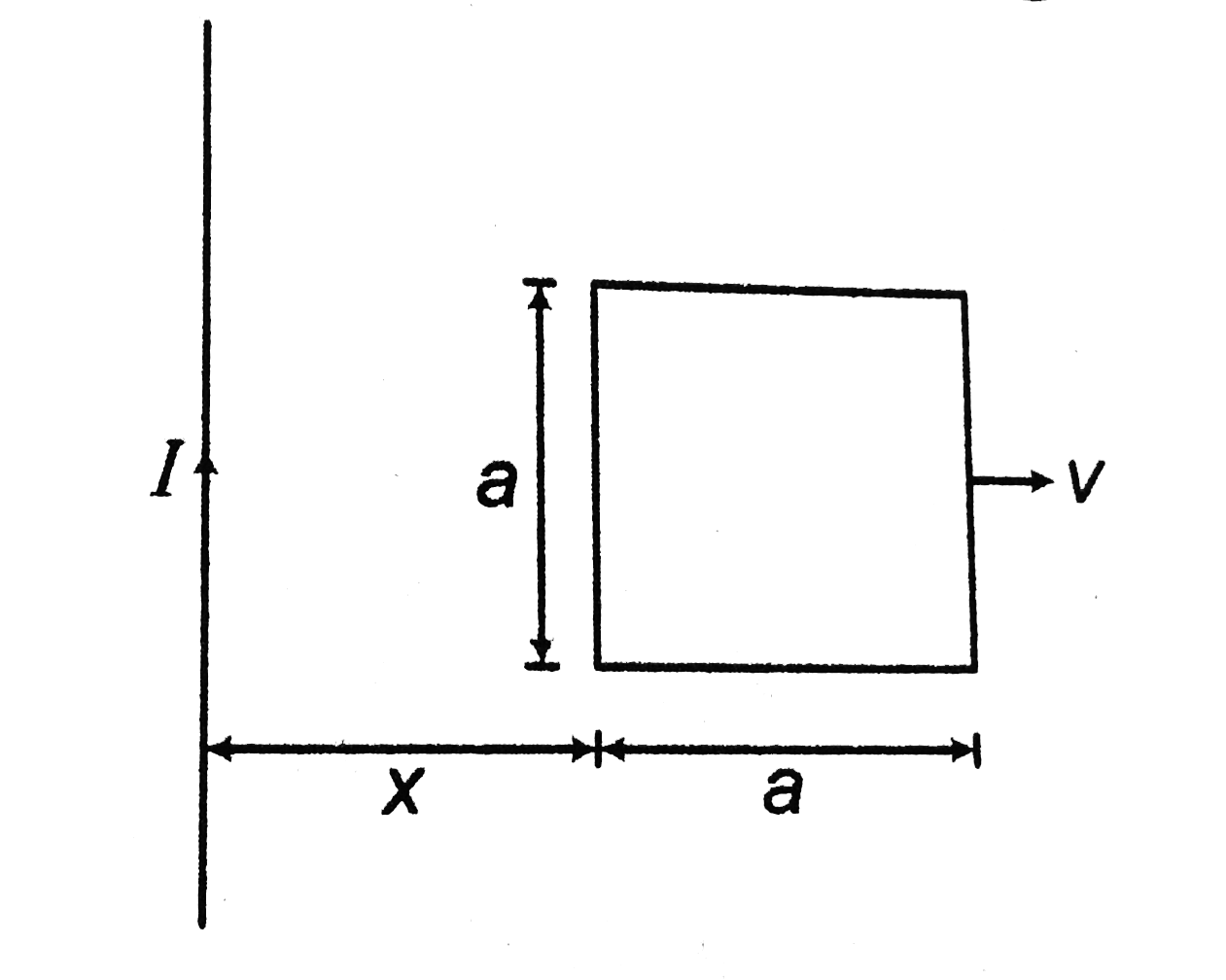
a Find induced emf produced i the loop as a function x
b. If total resistance of the loop is R, then find induced current in the loop,View SolutionA closed loop with the geometry shown in Fig. 3.9 is placed in a uniform magnetic field direction into the plane of the paper. If the magnetic field decreases with time, determine the direction of the induced emf in this loop.
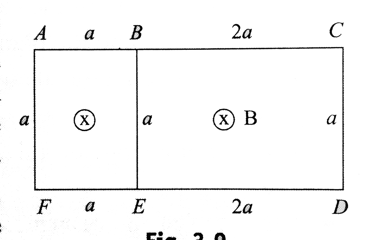 View Solution
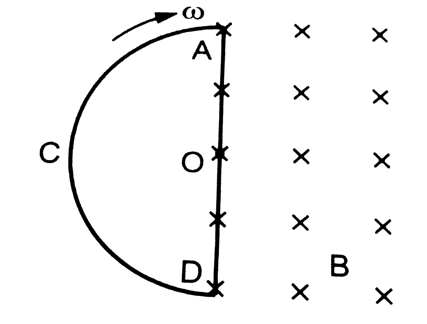
The magnetic field B shown in is directed into the plane of the paper. ACDA is a semicircular conducting loop of radius r with the centre at O. The loop is now made ot rotate clockwise with a constant angular velocity ω about on axis passing through O and perpendicular to the plane of the paper. The resistance of the loop is R. Obtain an expression for the magnitude of the induced current in the loop. Plot a graph between the induced current i and ωt, for two periods of rotation.
 View Solution
A triangular loop as shown in the figure is started to being pulled out at t=0 form a uniform magnetic field with a constant velocity v. Total resistancee of the loop is constant and equal to R. Then the variation of power produced in the loop with time will be :
 View Solution
An equilateral triangular loop ADC having some resistance is pulled with a constant velocity v out of a uniform magnetic field directed in to the paper. At time t=0, side DC of the loop at is at edge of the magnetic field.
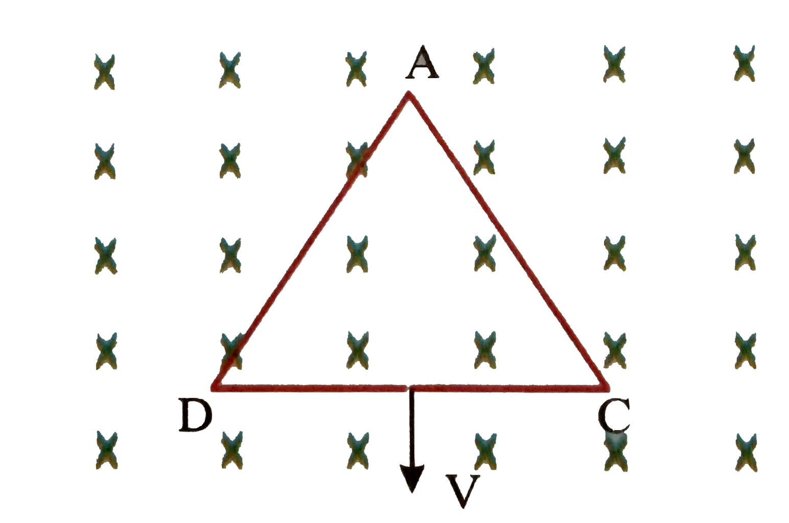
The induced current (i) versus time (t) graph will be asView Solution

