A closed loop with the geometry shown in Fig. 3.9 is placed in a uniform magnetic field direction into the plane of the paper. If the magnetic field decreases with time, determine the direction of the induced emf in this loop.
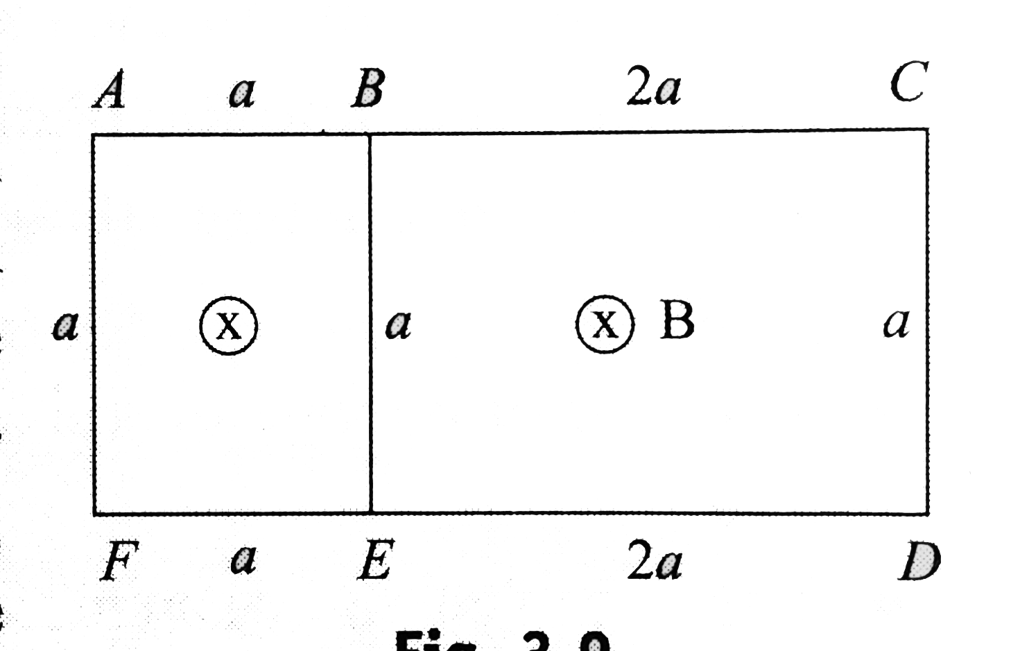
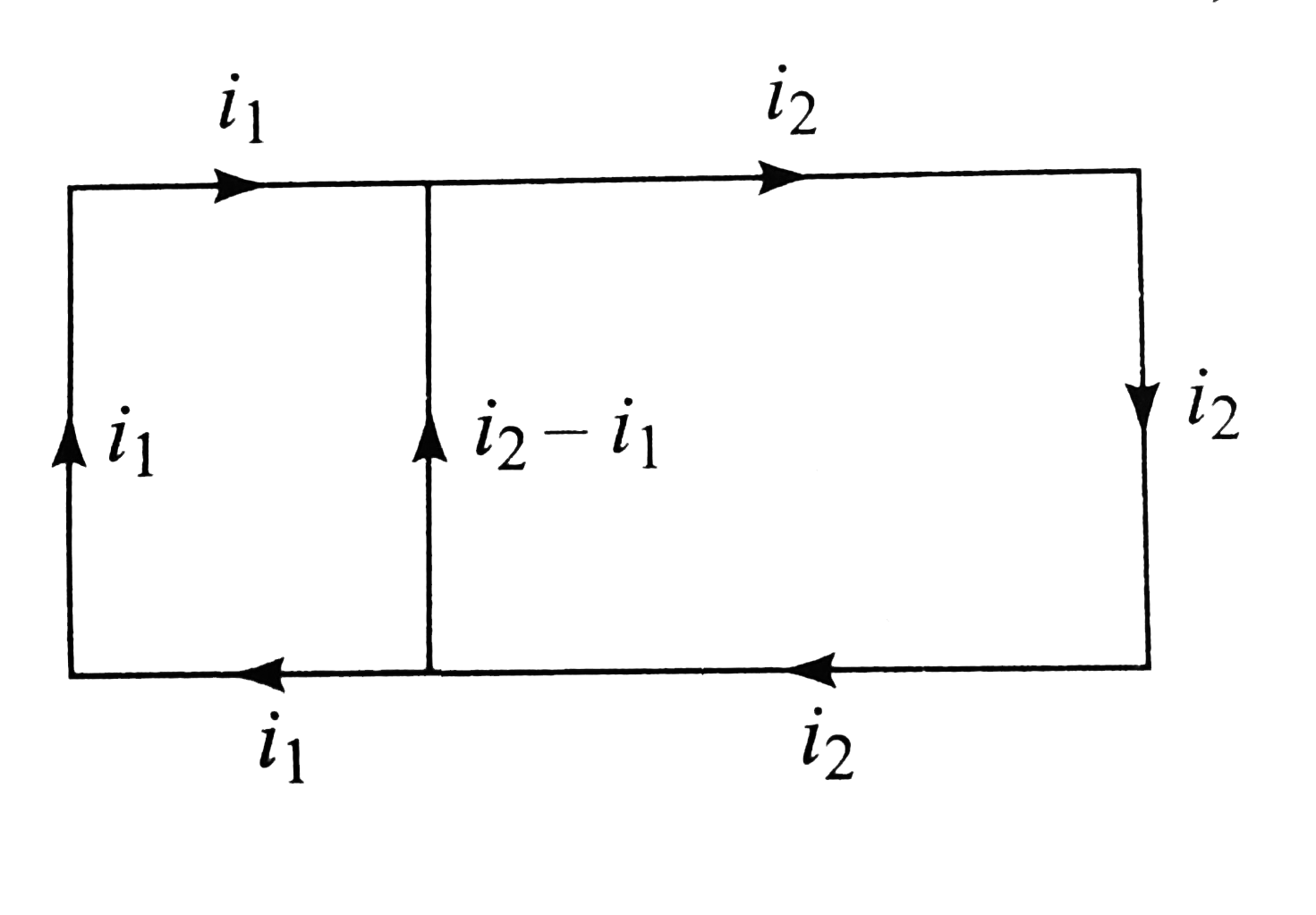
Therefore are two loops that are immersed in the magnetic in the field, namely. ABEFA and BCDEB.<br>Consrl∞pABEFA.Mag≠ticfluxis∫othepla≠paper.Forl∞pBCDEB→o,themag≠ticfluxis∫othepla≠ofthepaper.In⊥hl∞ps,themag≠ticfluxisdecreasingwithtime.<br>∴,the∈ducedcurrent∈l∞pABEFA,i_(1),willbe∈adirectionsoas→∈ducedafluxtn→thepaper.thedirectionofi_(1)isclockwise.<br>Likewise∈l∞pBCDEBthecurrenti_(2),willbe∈adirectionsoas→∈ducedafluxtn→thepaper.Thedirectionofi_(2) is also clockwise. The final induced current in all the arms of the loop are shown in Fig.3.10.
Topper's Solved these Questions
- ELECTROMAGNETIC INDUCTIONBOOK - CENGAGE PHYSICS ENGLISHCHAPTER - ELECTROMAGNETIC INDUCTIONEXERCISE - Solved Example
5 Videos
- ELECTROMAGNETIC INDUCTIONBOOK - CENGAGE PHYSICS ENGLISHCHAPTER - ELECTROMAGNETIC INDUCTIONEXERCISE - Exercise 3.1
15 Videos
- ELECTRICAL MEASURING INSTRUMENTSBOOK - CENGAGE PHYSICS ENGLISHCHAPTER - ELECTRICAL MEASURING INSTRUMENTSEXERCISE - M.C.Q
2 Videos
- ELECTRON,PHONTS,PHOTOELECTRIC EFFECT & X-RAYSBOOK - CENGAGE PHYSICS ENGLISHCHAPTER - ELECTRON,PHONTS,PHOTOELECTRIC EFFECT & X-RAYSEXERCISE - dpp 3.3
15 Videos
Similar Questions
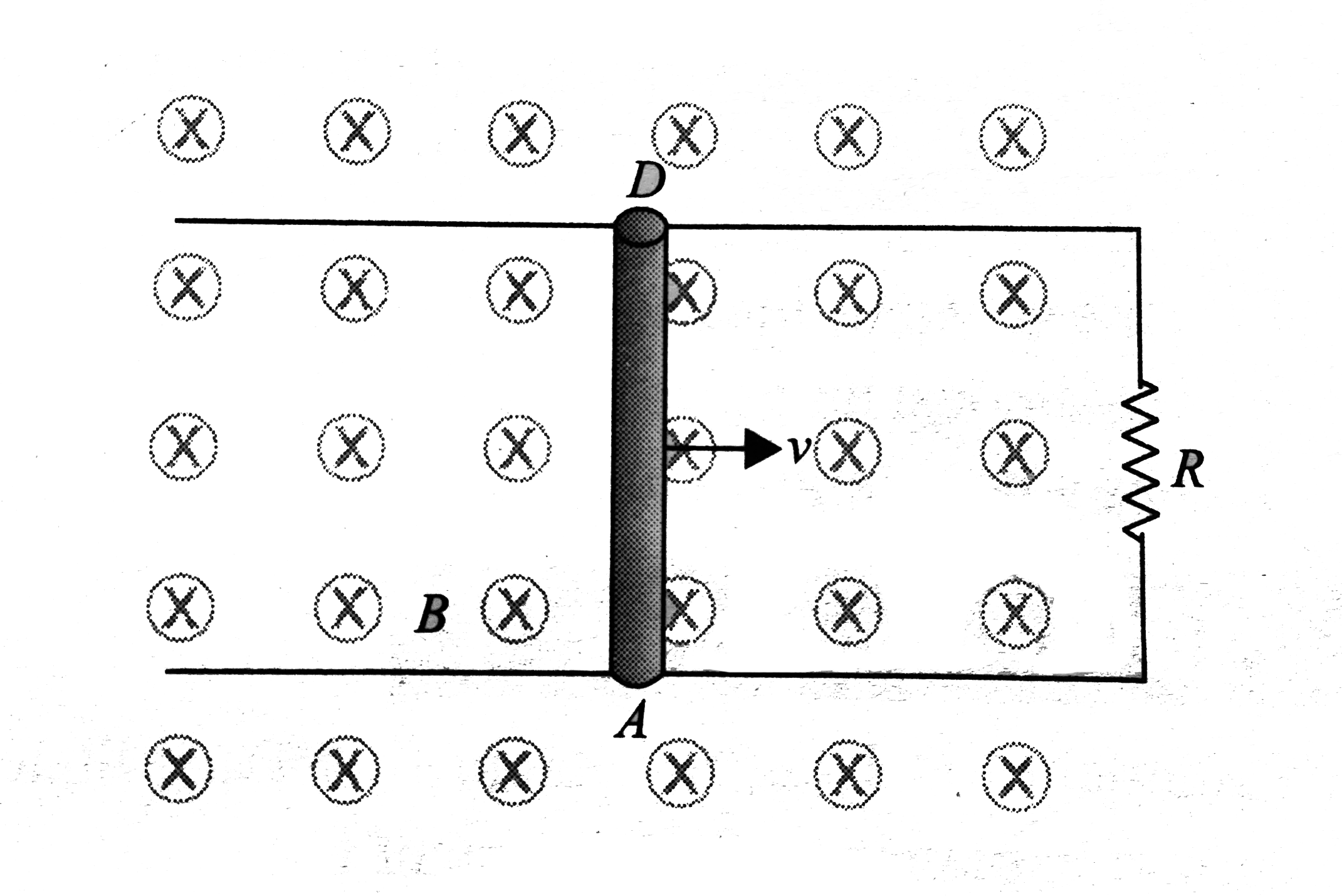
The counductor AD moves to the right in a uniform magnetic field directed into the plane of the paper.
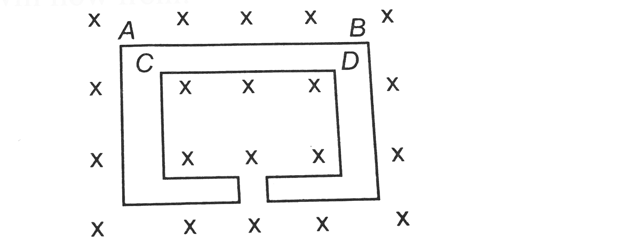
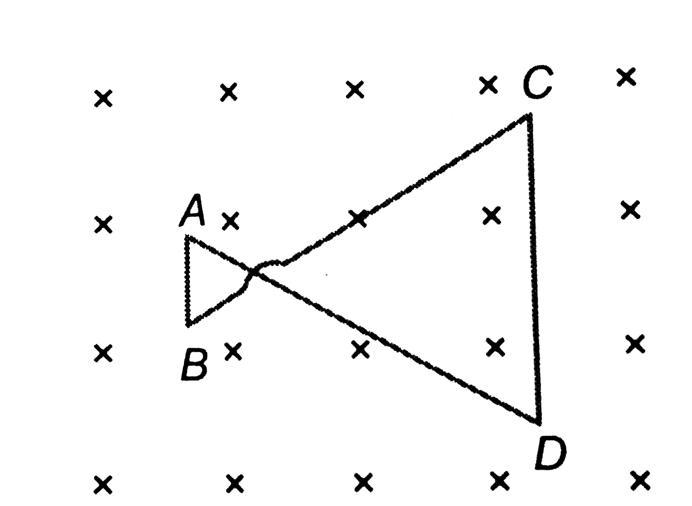
View SolutionA wire is bent to form the double loop shown in figure. There is a uniform magnetic field directed into the plane of the loop. If the magnitude of this field is decreasing current will flow from:
View Solution
Knowledge Check
A conducting ring is placed in a uniform magnetic field with its plane perpendicular to the field . An emf is induced in the ring if
Ait is rotated about its axis.Bit is rotated about its diameter.Cit is not moved.Dit is given translational motion in the field.
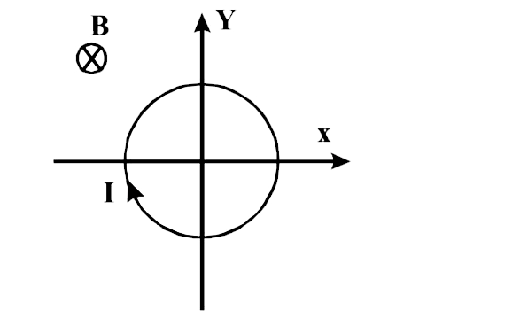
A conducting loop carrying a current I is placed in a uniform magnetic field ponting into the plane of the paper as shown. The loop will have a tendency to
View SolutionA conducting wire frame is placed in a magnetic field which is directed into the paper. The magnetic field is increasing at a constant rate. The directions of induced currents in wires AB and CD are
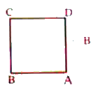
View SolutionA conducting wire frame is placed in a magnetic field which is directed into the paper. The magnetic field is increasing at a constant rate. The direction of induced current in wire AB and CD are
View SolutionA metallic loop is placed in a nonuniform magnetic field. Will an emf be induced in the loop?
View SolutionA current carrying loop in a uniform magnetic field will experience
View SolutionA loop of irregular shape of conducting wire PORS (as shown in figure) placed in a uniform magnetic field perpendicular to the plane of the paper changes into a circular shape. The direction of induced current will be
View SolutionIn non-uniform magnetic field in certain direction, current loop is placed
View Solution
