The net resistance between points P and Q in the circuit shown in figure is
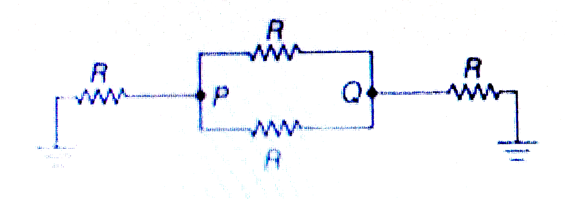
A
R/2
B
2R/5
C
3R/5
D
R/3
Video Solution
Text Solution
The correct Answer is:B
|
Answer
Step by step video & image solution for The net resistance between points P and Q in the circuit shown in figure is by Physics experts to help you in doubts & scoring excellent marks in Class 11 exams.
Updated on:21/07/2023Topper's Solved these Questions
Similar Questions
Knowledge Check
The equivalent resistance between A and B for . the circuit shown in this figure is
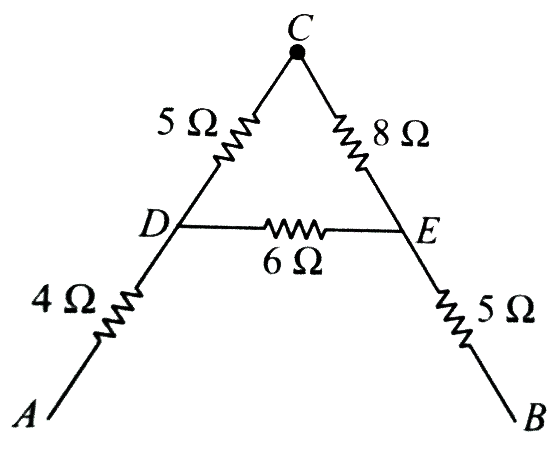 A13.1ΩB15.1ΩC17.1ΩD19.1Ω
The equivalent resistance between points a and f of the network shown in figure below is
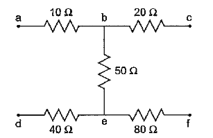 A24ΩB110ΩC140ΩD200Ω
What is the equivalent resistance between point A and C in the circuit shown in fig. ?

View SolutionCalculate the equivalent resistance between the points A and B in the circuit shown in Fig. (a)

View SolutionFind the net resistance between A and B in the circuit.
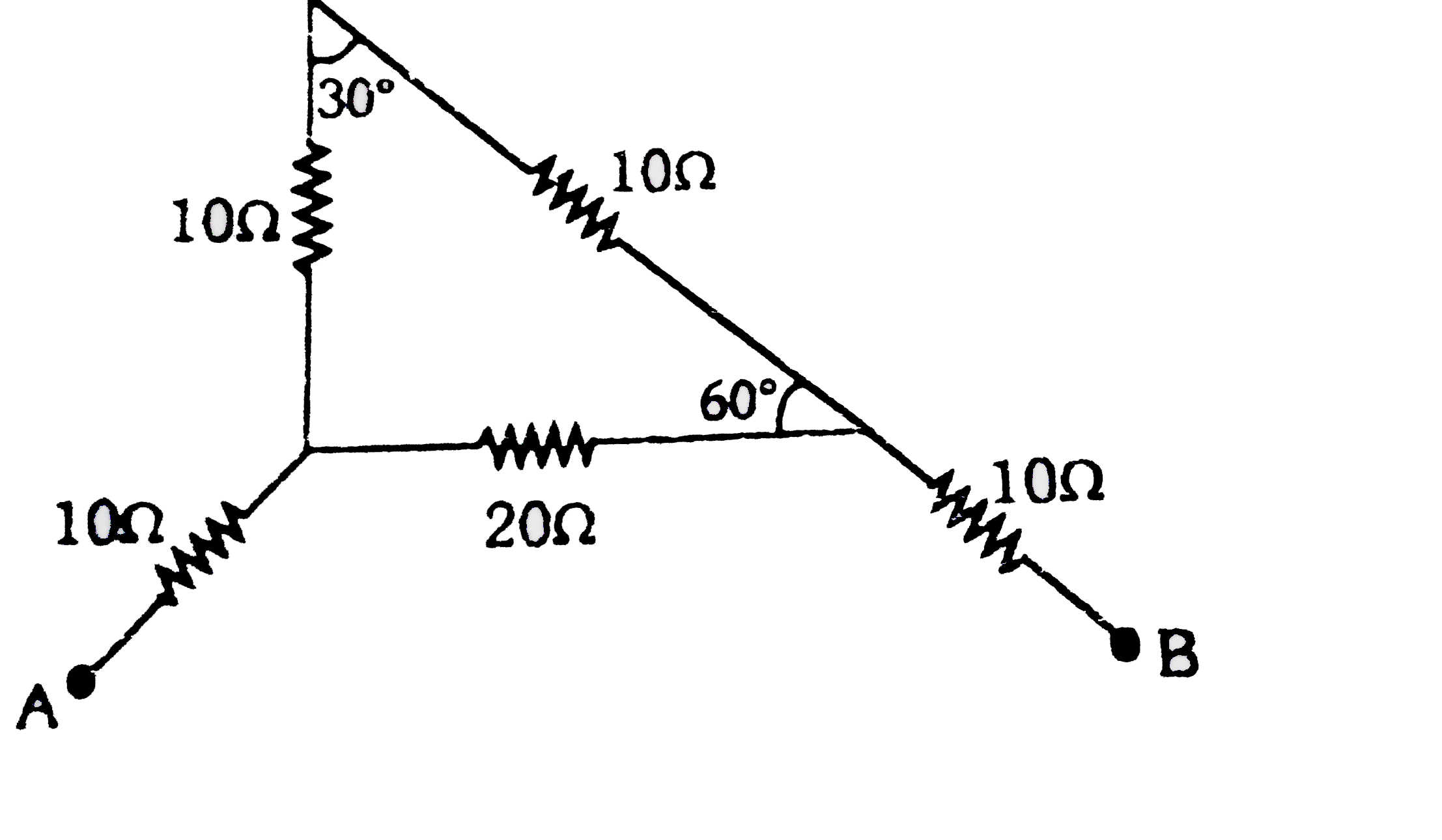
View SolutionCalculate the effective resistance between the points A and B in the circuit shown in Fig.
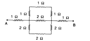
View SolutionFind equivalent resistance between points A and B in the circuit shown. All resistances are equal toR.
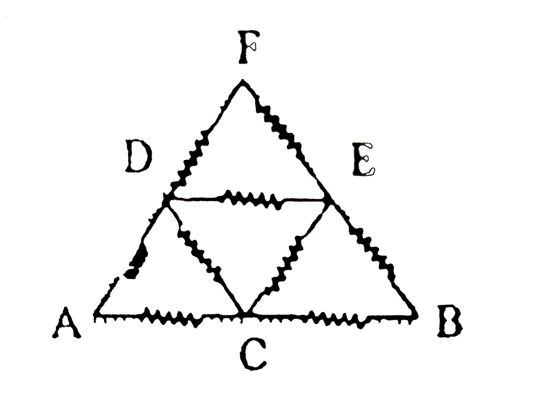
View SolutionThe equivalent resistance across points A and B , in the circuit shown in the figure , is
_PHY_E01_017_Q01.png)
View Solution
_PHY_E05_095_Q01.png)
_PHY_E05_041_Q01.png)