In the non-resonant circuit, what will be the nature of the circuit for frequencies heigher than the resonant frequency?
Resistive
Capacitive
inductance
None of these
The correct Answer is:C
To determine the nature of a non-resonant circuit for frequencies higher than the resonant frequency, we can follow these steps:
1. Understanding the Circuit:
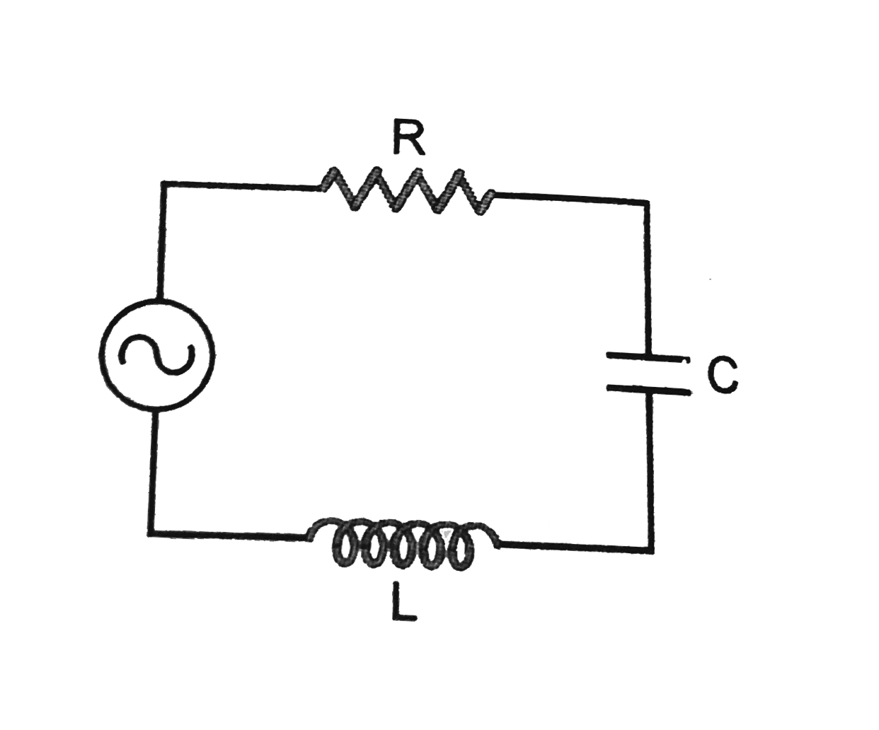
- We are dealing with an LCR (Inductor-Capacitor-Resistor) circuit. The components involved are a resistor (R), an inductor (L), and a capacitor (C).
2. Identifying Resonant Frequency:
- The resonant frequency (ω_R) is the frequency at which the inductive reactance (ωL) and capacitive reactance (1/ωC) are equal. At this frequency, the circuit behaves like a purely resistive circuit.
3. Analyzing Frequencies Above Resonant Frequency:
- When the frequency (ω) is greater than the resonant frequency (ω > ω_R), we need to analyze the behavior of the circuit.
- The inductive reactance (X_L = ωL) increases with frequency, while the capacitive reactance (X_C = 1/ωC) decreases with frequency.
4. Comparing Reactances:
- For ω > ω_R:
- X_L (inductive reactance) becomes larger because it is directly proportional to ω.
- X_C (capacitive reactance) becomes smaller because it is inversely proportional to ω.
5. Conclusion on Circuit Nature:
- Since the inductive reactance (X_L) dominates over the capacitive reactance (X_C) when ω > ω_R, the circuit behaves more like an inductive circuit.
- Therefore, in a non-resonant circuit with frequencies higher than the resonant frequency, the nature of the circuit is inductive.
Final Answer:
The nature of the circuit for frequencies higher than the resonant frequency in a non-resonant circuit is inductive.
---
- We are dealing with an LCR (Inductor-Capacitor-Resistor) circuit. The components involved are a resistor (R), an inductor (L), and a capacitor (C).
- The resonant frequency (ω_R) is the frequency at which the inductive reactance (ωL) and capacitive reactance (1/ωC) are equal. At this frequency, the circuit behaves like a purely resistive circuit.
- When the frequency (ω) is greater than the resonant frequency (ω > ω_R), we need to analyze the behavior of the circuit.
- The inductive reactance (X_L = ωL) increases with frequency, while the capacitive reactance (X_C = 1/ωC) decreases with frequency.
- For ω > ω_R:
- X_L (inductive reactance) becomes larger because it is directly proportional to ω.
- X_C (capacitive reactance) becomes smaller because it is inversely proportional to ω.
- Since the inductive reactance (X_L) dominates over the capacitive reactance (X_C) when ω > ω_R, the circuit behaves more like an inductive circuit.
- Therefore, in a non-resonant circuit with frequencies higher than the resonant frequency, the nature of the circuit is inductive.
The nature of the circuit for frequencies higher than the resonant frequency in a non-resonant circuit is inductive.
Similar Questions
Assertion : In series L−C−R circuit, voltage will lead the current function for frequency greater than the resonance frequency.
Reason : At resonance frequency, phase difference between current function and voltage function is zero.View SolutionWhat is resonance ? What is resonant frequency ?
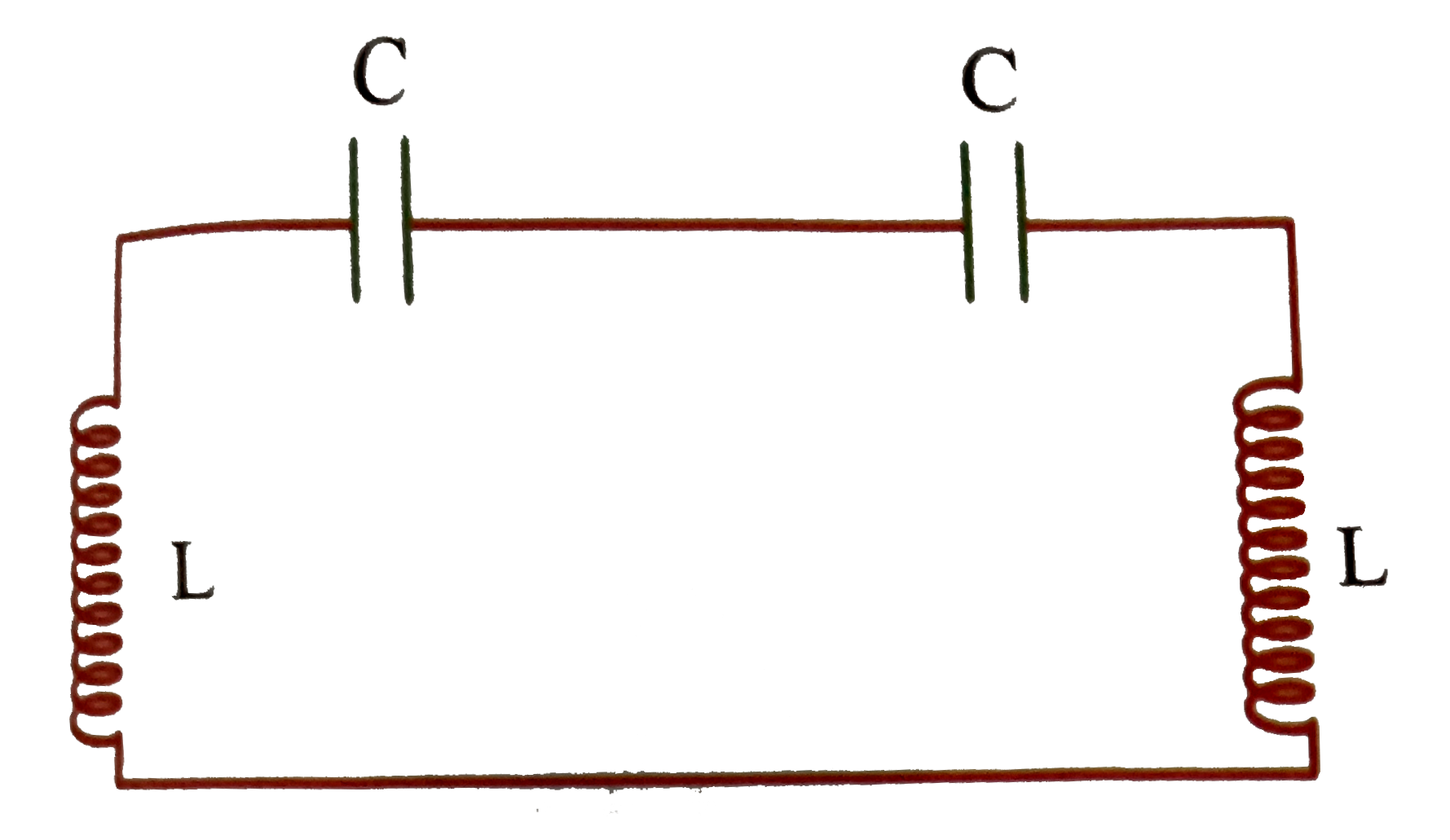
View SolutionThe natural frequency of the circuit shown in the figure is
 View Solution
Current through an AC series L-C-R circuit is 2 A if operated at resonance frequency , and 1 A if operated at 50% less than resonant frequency . The current (in A) if the frequency is 100% more than the resonant frequency , is
A.√2 B.1 C.√3 D.Data insufficientView SolutionIn a series L-C-R circuit shown in the figure , what is the resonance frequency and the current at the resonating frequency?
View SolutionIn a series LCR circuit, obtain an expression for the resonant frequency.
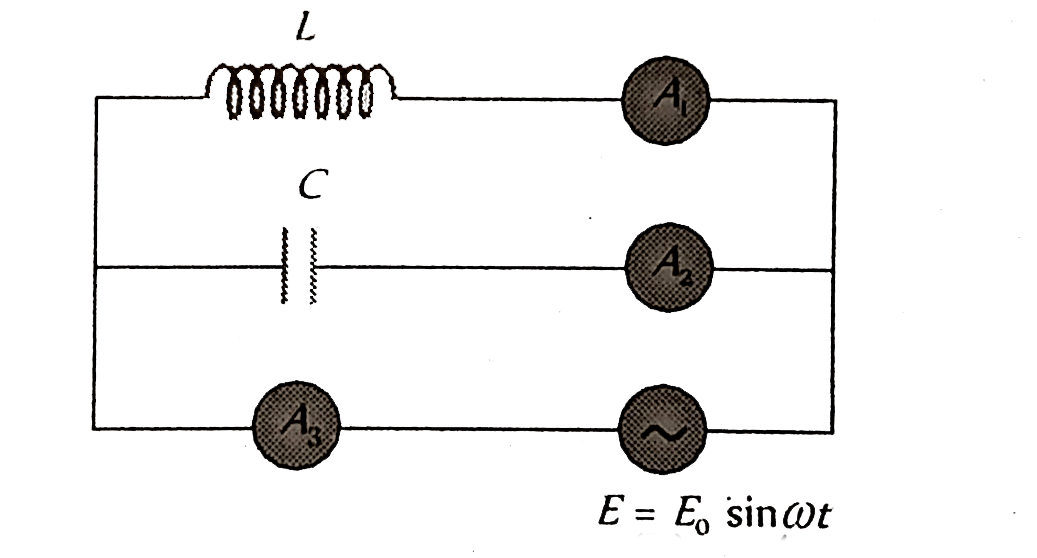
View SolutionAn inductor L and a capacitor C are connected in the circuit as shown in the figure. The frequency of the power supply is equal to the resonant frequency of the circuit. Which ammeter will read zero ampere
 View Solution
In a series LCR circuit, impedance Z is same at two frequencies f1 and f2. Therefore, the resonant frequency of this circuit is
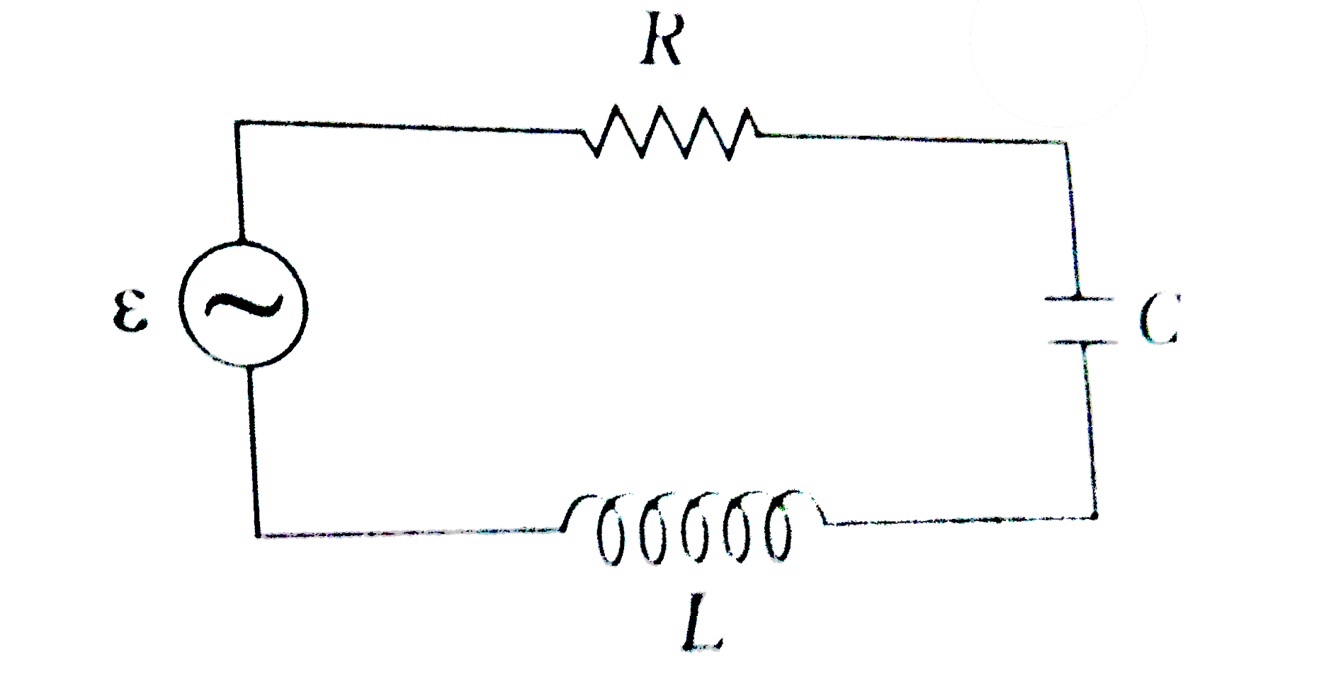
View SolutionFigure here, shows a series L-C-R circuit connected to a variable frequency 230 V source. L = 5.0H, C = 80μF and r =40Ω
(a) Determine the source frequency which drives the circuit in resonance.
(b) Obtain the impedance of the circuit and the amplitude of current at the resonating frequency.
(c) Determine the rms potential drops across the three elements of the circuit. show that the potential drop across the L-C combination is zero at the resonating frequency.
 View Solution
A series LCR circuit connected to a variable frequency 230 V source has L = 5.0 H, C=80μF, R=40Ω, Fig.
(a) Determine the source frequency which drives the circuit in resonance.
(b) Obtain the impedance of the circuit and amplitude of current at at resonating frequency.
(c ) Determine the r.m.s. potential drops acorss the three elements the circuits. Show that the potential drop acorss the LC combination is zero at the resonating frequecny.
 View Solution

