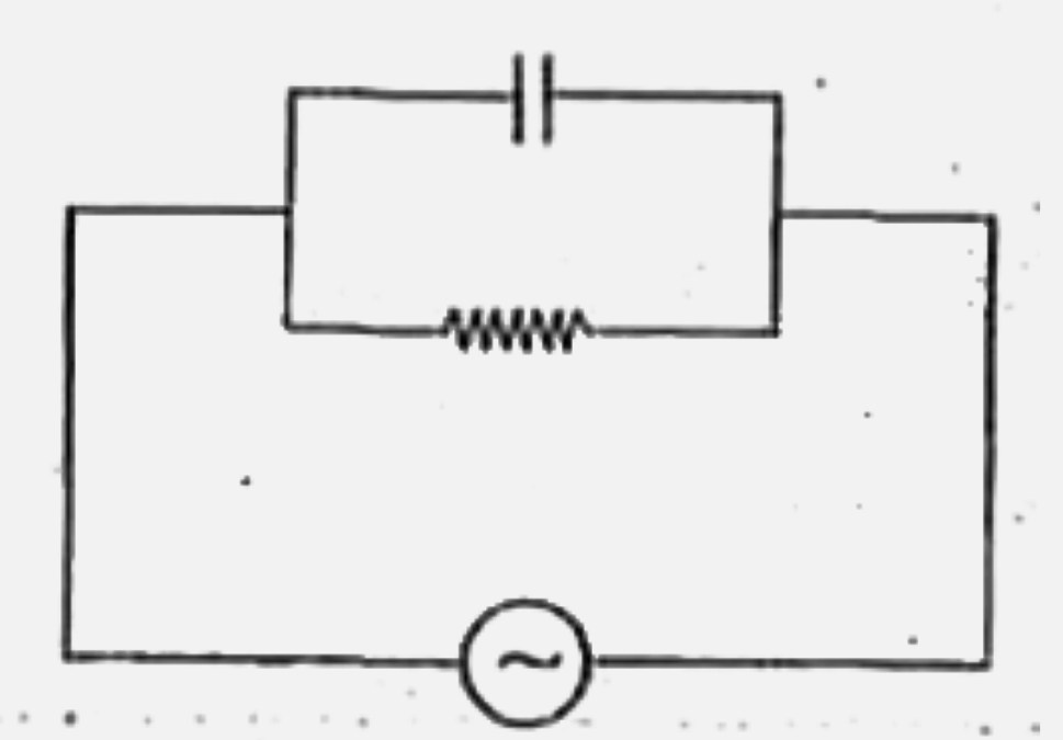
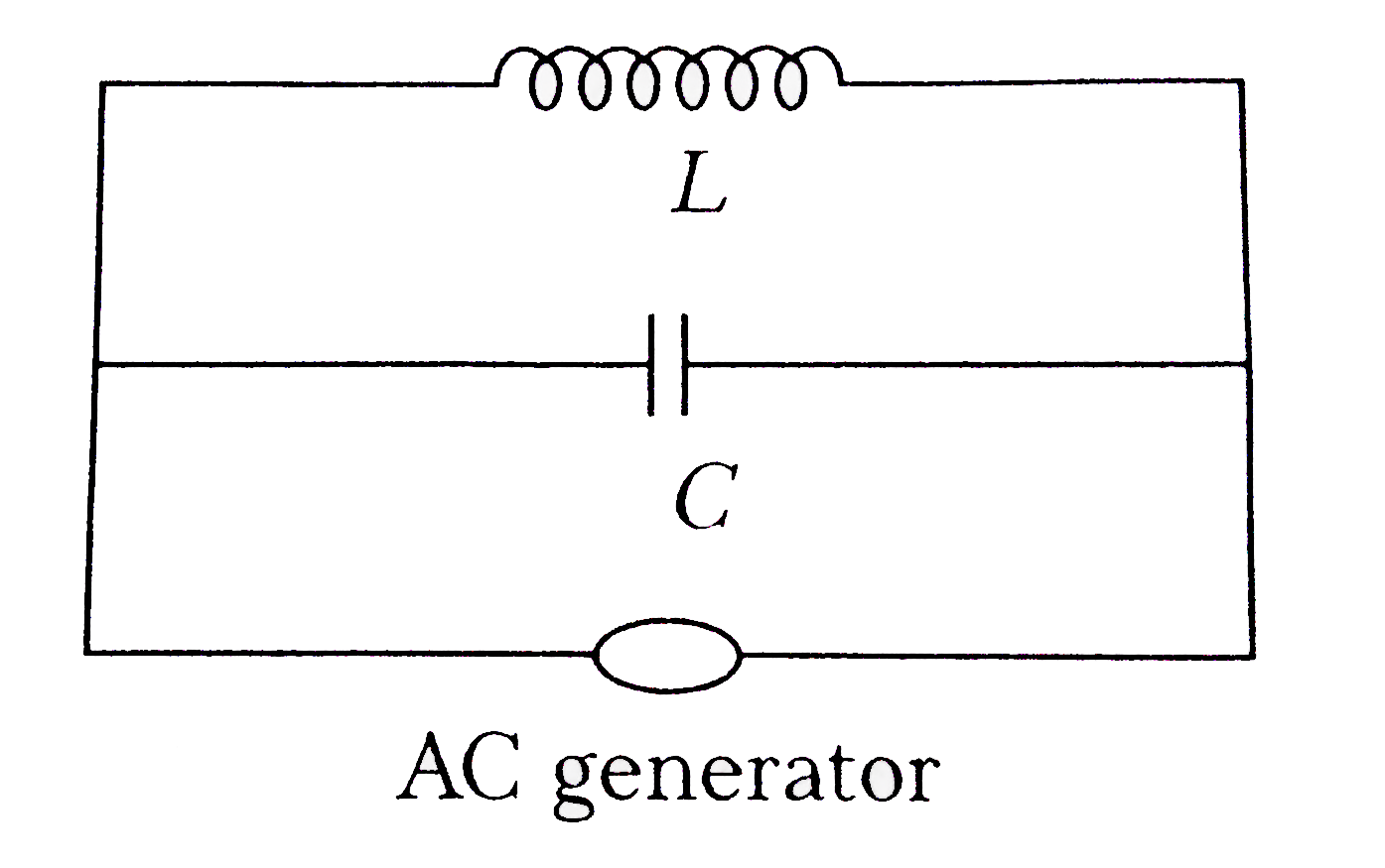
In the circuit shown in the figure , the alternating currents through inductor and capacitor are 1.2 and 1.0 A respectively . The current drawn from the generator is
A
0.4 A
B
0.2 A
C
1.0 A
D
1.2 A
Video Solution
Text Solution
The correct Answer is:B
|
Answer
Step by step video & image solution for In the circuit shown in the figure , the alternating currents through inductor and capacitor are 1.2 and 1.0 A respectively . The current drawn from the generator is by Physics experts to help you in doubts & scoring excellent marks in Class 12 exams.
Updated on:21/07/2023Similar Questions
Knowledge Check
In the circuit shown in figure the current flowing through 25 V cell is
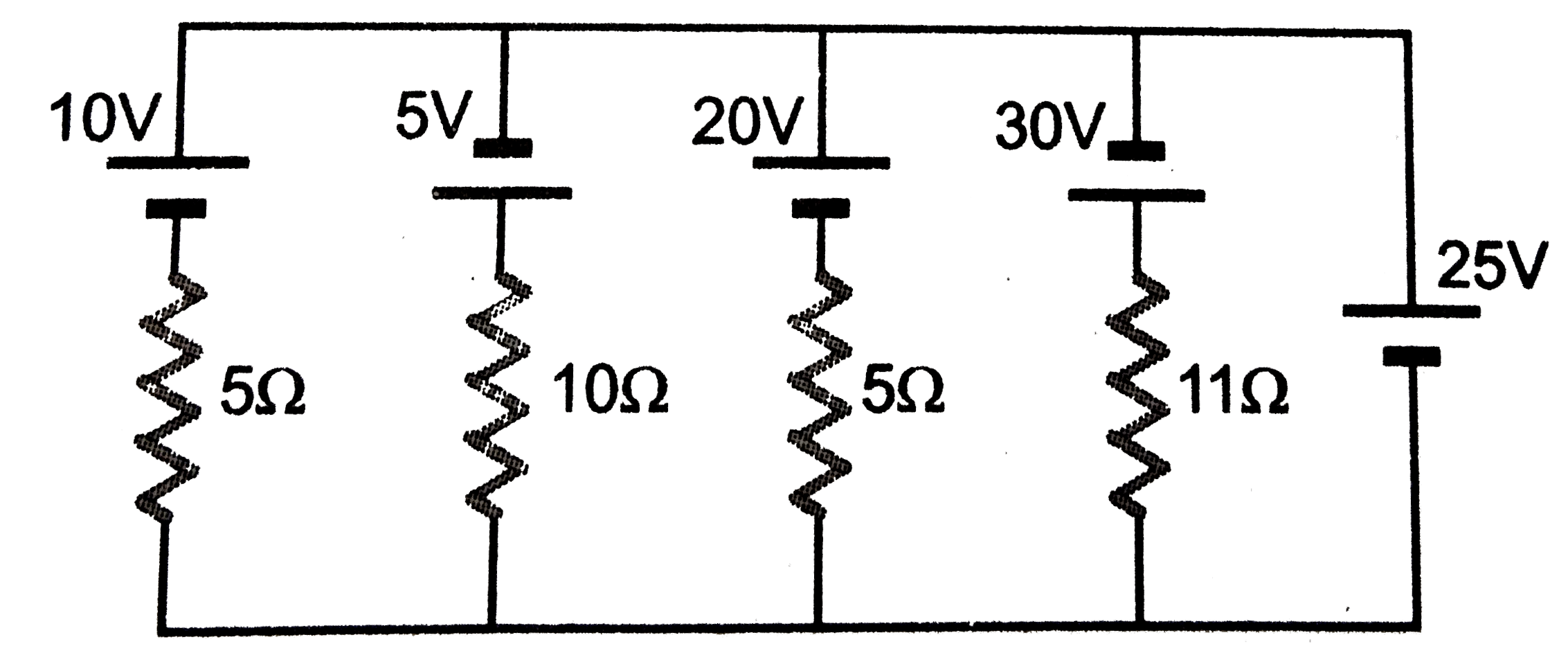 A7.2AB10AC12AD14.2A
In the circuit shown in figure the current flowing through 25 V cell is
 A7.2AB10AC12AD14.2A
In the circuit shown in figure the current through
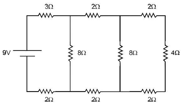
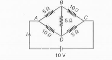
View SolutionIn the circuit shown in figure, the current / in circuit is
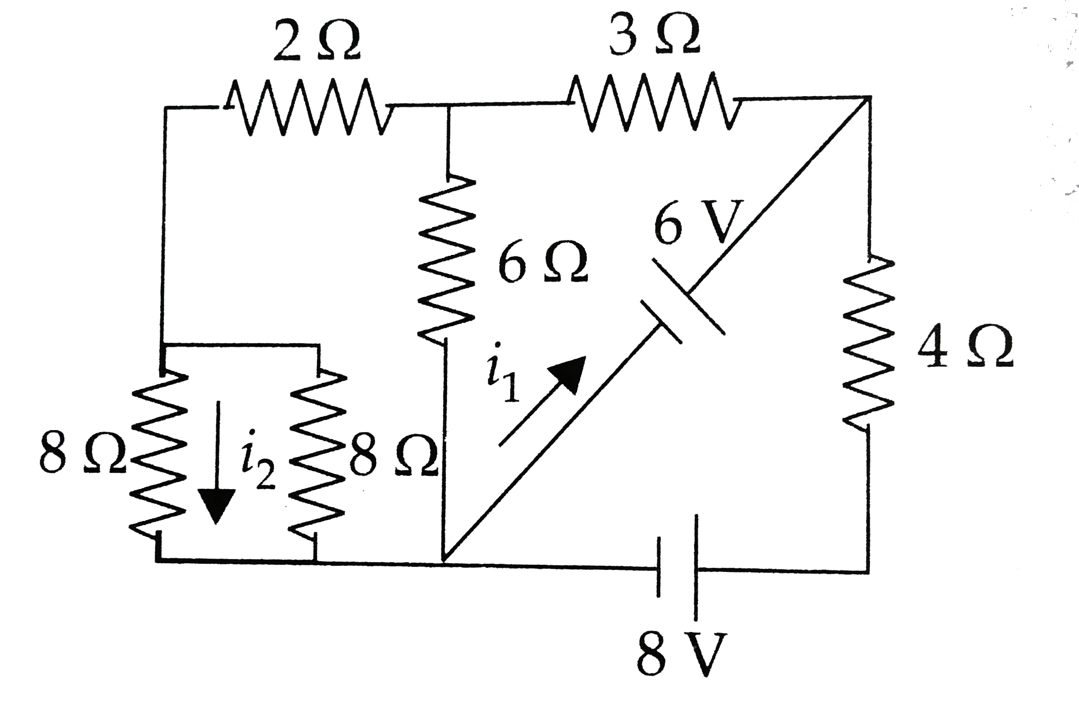
View SolutionIn the circuit as shown in figure, the ratio of current i1/i2 is
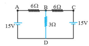
View SolutionIn the circuit shown in figure, find the current through the branch BD.
View SolutionIn the circuit shown in figure ,find the ratio of currents i1/i2.
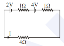
View SolutionFor the circuit shown in the figure current I will be
View Solution

