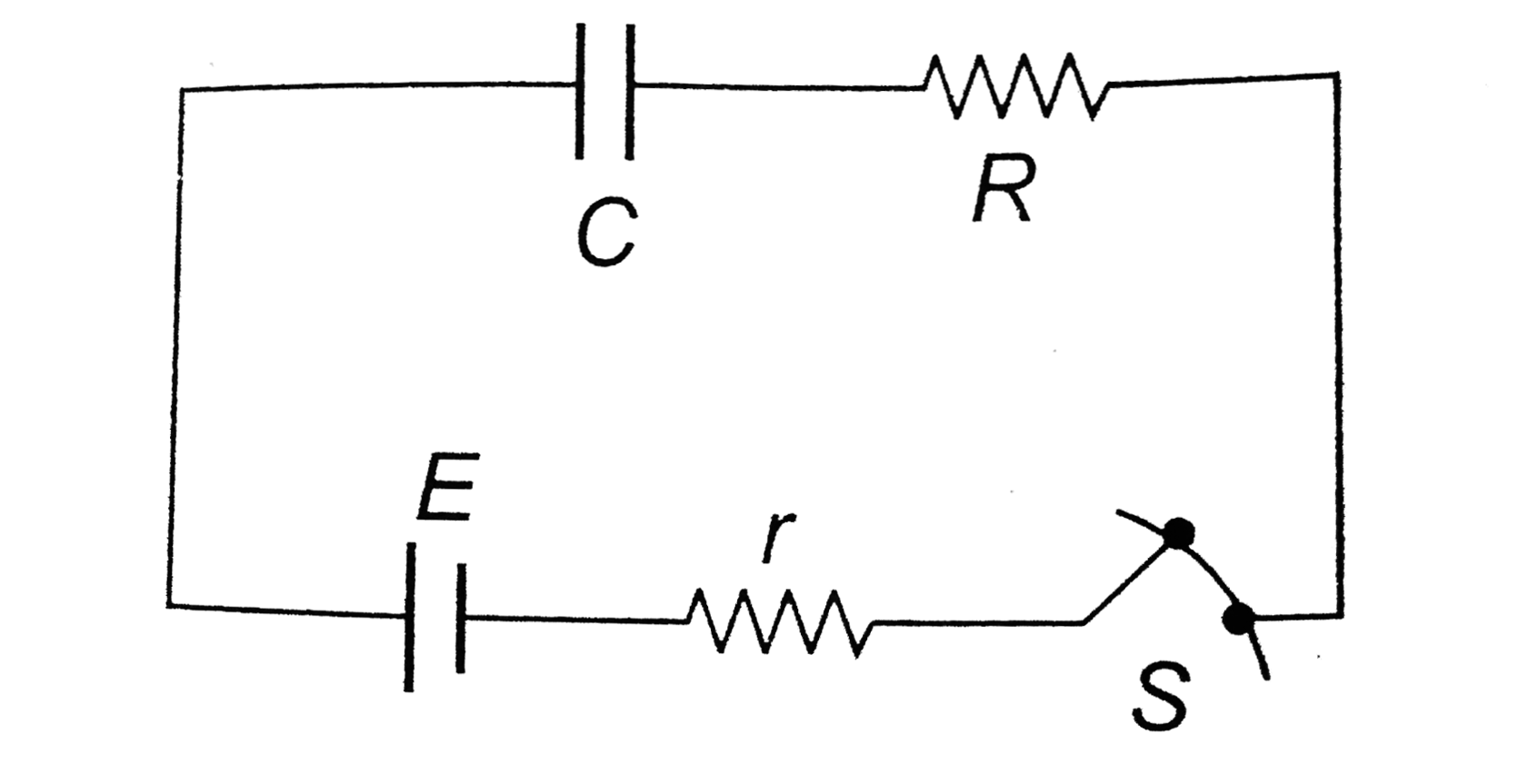
Assertion : The switch S shown in the figure is closed at t=0. Initial current flowing through battery is ER+r
Reason : Initially capacitor was uncharged, so resistance offered by capacitor at t=0 is zero
Statement I is true, Statement II is True, Statement II is a correct explanation for Statement I.
Statement I is True, Statement II is True, Statement II is not a correct explanation for Statement I.
Statement I is True, Statement II is False.
Statement I is False, Statement II is True.
The correct Answer is:A
a. Charge on capacitor q=CE(1−e−t/CReq)
∴I=dqdt=EReqe−t/CR
at t=0,I=EReq=ER+r
Therefore, resistance offered by the capacitor is zero.
Topper's Solved these Questions
- BOOK - CENGAGE PHYSICS ENGLISHCHAPTER - MISCELLANEOUS VOLUME 3EXERCISE - Integer Answer Type11videos
MISCELLANEOUS VOLUME 3
- BOOK - CENGAGE PHYSICS ENGLISHCHAPTER - MISCELLANEOUS VOLUME 3EXERCISE - True and False3videos
MISCELLANEOUS VOLUME 3
- BOOK - CENGAGE PHYSICS ENGLISHCHAPTER - MISCELLANEOUS VOLUME 3EXERCISE - Multiple correct Answer type109videos
MISCELLANEOUS VOLUME 3
- BOOK - CENGAGE PHYSICS ENGLISHCHAPTER - MAGNETIC FIELD AND MAGNETIC FORCESEXERCISE - Multiple Correct Answer type2videos
MAGNETIC FIELD AND MAGNETIC FORCES
- BOOK - CENGAGE PHYSICS ENGLISHCHAPTER - MISCELLANEOUS VOLUME 5EXERCISE - Integer12videos
MISCELLANEOUS VOLUME 5
Similar Questions
The switch shown in figure is closed at t=0 find the charge throuh battery till time t=LR
_2019_CBT8_E01_016_Q01.png) View Solution
View SolutionThe switch shown in figure is closed at t=0 find the charge throuh battery till time t=LR
_2019_CBT8_E01_016_Q01.png) View Solution
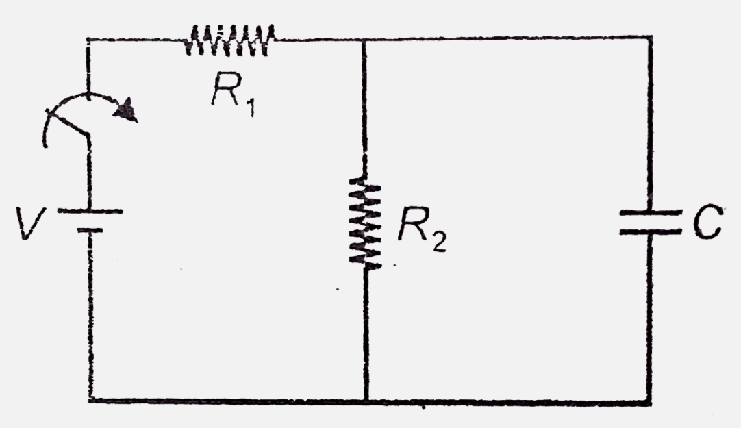
View SolutionConsider the circuit shown. Switch is closed at t=0. Find the current through the battery as a function of time. Initially capacitor was uncharged.
 View Solution
Switch is closed at t=0 then the current in the circuit at t=L2R is
_PHY_E06_157_Q01.png) View Solution
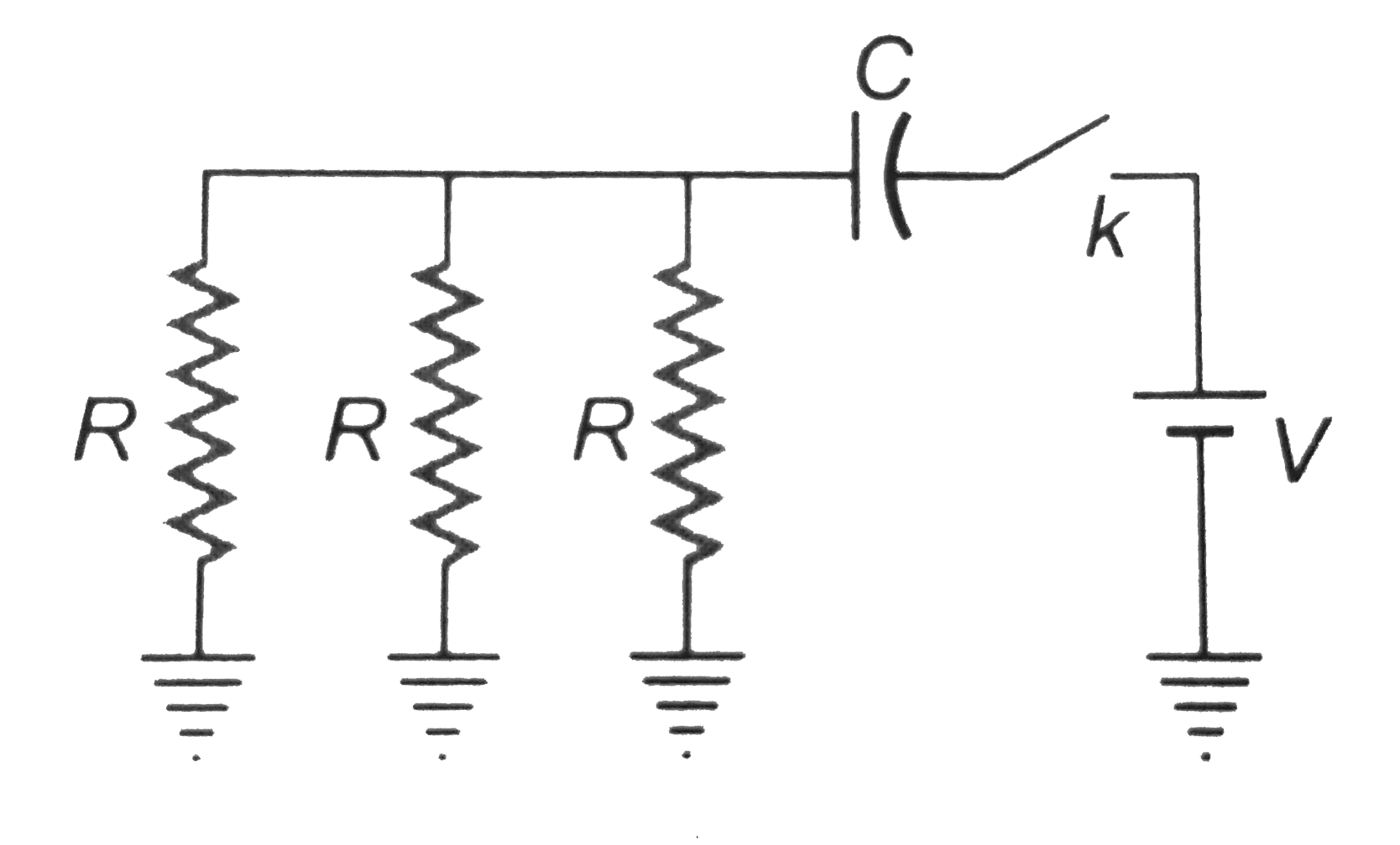
View SolutionThe switch shown n the figure is closed at t=0. The charge on the capacitor as a function of time is given by
 View Solution
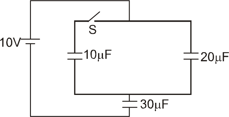
Charge flow through the battery after closing the switch is (initially all capacitors are uncharged) :
 View Solution
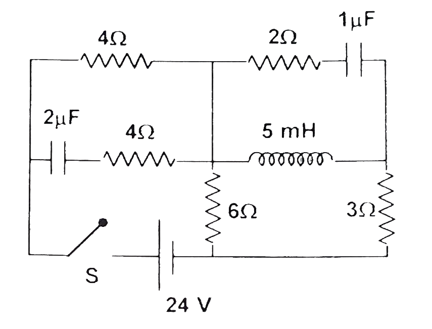
In the circuit shown, the switch 'S' is closed at t=0. Then the current through the battery steady state reached is
 View Solution
In the circuit shown in figure switch S is closed at time t=0
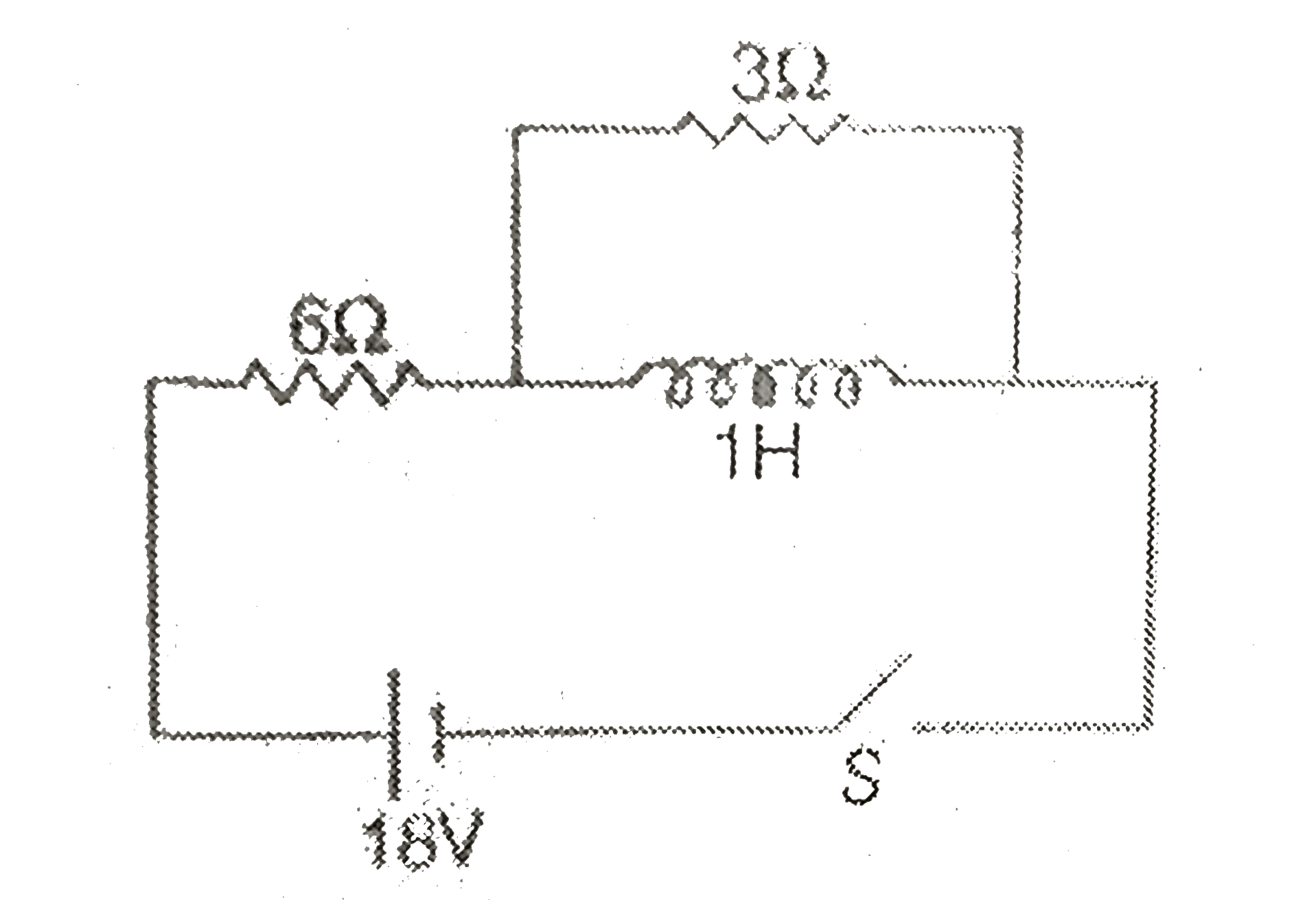
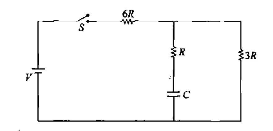
Current I from the battery at time t is given byView SolutionIn the circuit shown in figure-3.240 switch S is closed at time t=0. find the current through different wires and charge stored on the capacitor at any time t.
 View Solution
For the circuit shown in figure below, at t = 0, switch is closed, the initial current through resistor and final charge on capacitor are
 View Solution

