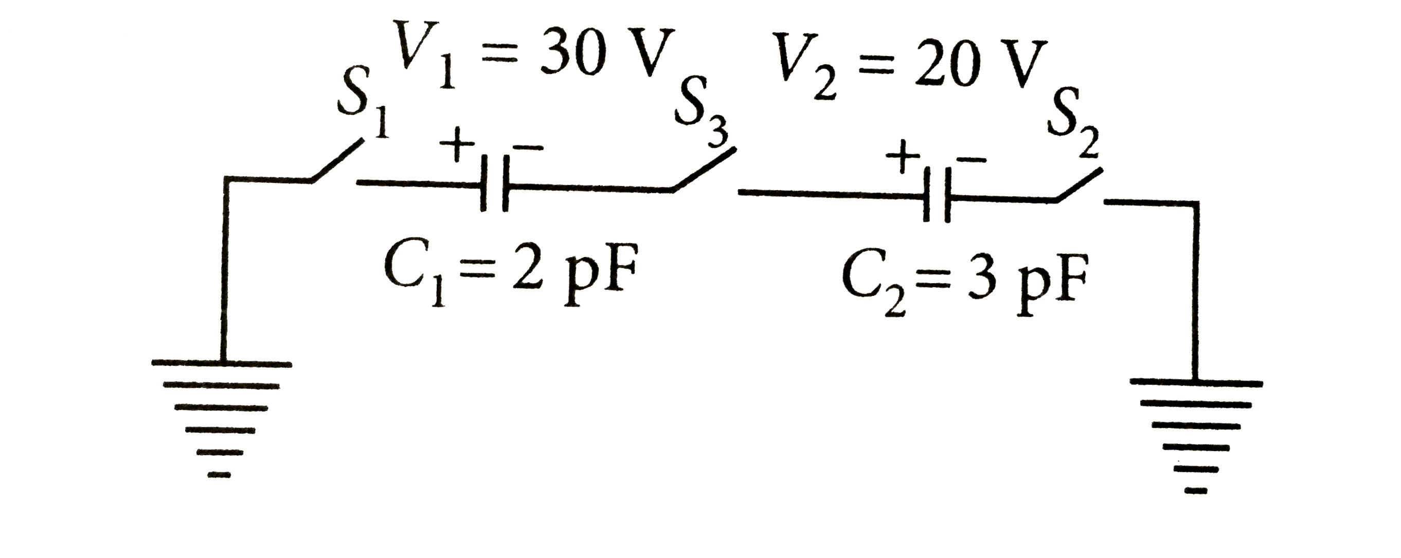
For the circuit shown in figure, which of the following statements is ture ?
A
Its time constant is 0.25s
B
In steady state, current through the inductance will be equal to zero
C
In steady state, current through the battery will be equal to 0.75A
D
None of these
Video Solution
Text Solution
The correct Answer is:A, C
In the circuit shows in the figure in problem, 6Ω and 12Ω resistances are in parallel with each other and their parallel combination is in series with 4Ω and the inductance of 2H. Hence, equivalent resistance of these three resistance is equal to 8Ω.
Therefore, the time constant for the circuit is
λ=LR=28=0.25s
Hence (a) is correct.
In steady state, no e.m.f. will be incuced in the inductance. Hence current through the circuit will be equal to E/R where R is the equivalent resistance. Hence, the steady state current will be equal
to 6/8=0.75A.
Hence (c ) is correct and (b) is wrong.
|
Updated on:21/07/2023
Topper's Solved these Questions
- BOOK - CENGAGE PHYSICS ENGLISHCHAPTER - INDUCTANCEEXERCISE - Exercises (assertion-reasoning)2videos
INDUCTANCE
- BOOK - CENGAGE PHYSICS ENGLISHCHAPTER - INDUCTANCEEXERCISE - Exercises (linked Compreshension)36videos
INDUCTANCE
- BOOK - CENGAGE PHYSICS ENGLISHCHAPTER - INDUCTANCEEXERCISE - Exercises (single Correct )65videos
INDUCTANCE
- BOOK - CENGAGE PHYSICS ENGLISHCHAPTER - HEATING EFFECT OF CURRENTEXERCISE - Thermal Power in Resistance Connected in Circuit27videos
HEATING EFFECT OF CURRENT
- BOOK - CENGAGE PHYSICS ENGLISHCHAPTER - MAGNETIC FIELD AND MAGNETIC FORCESEXERCISE - Multiple Correct Answer type2videos
MAGNETIC FIELD AND MAGNETIC FORCES
Similar Questions
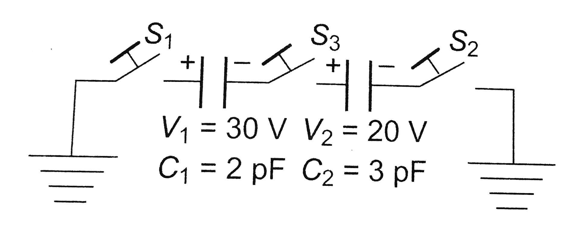
For the circuit shown in figure, which of the following statements is true ?
 View Solution
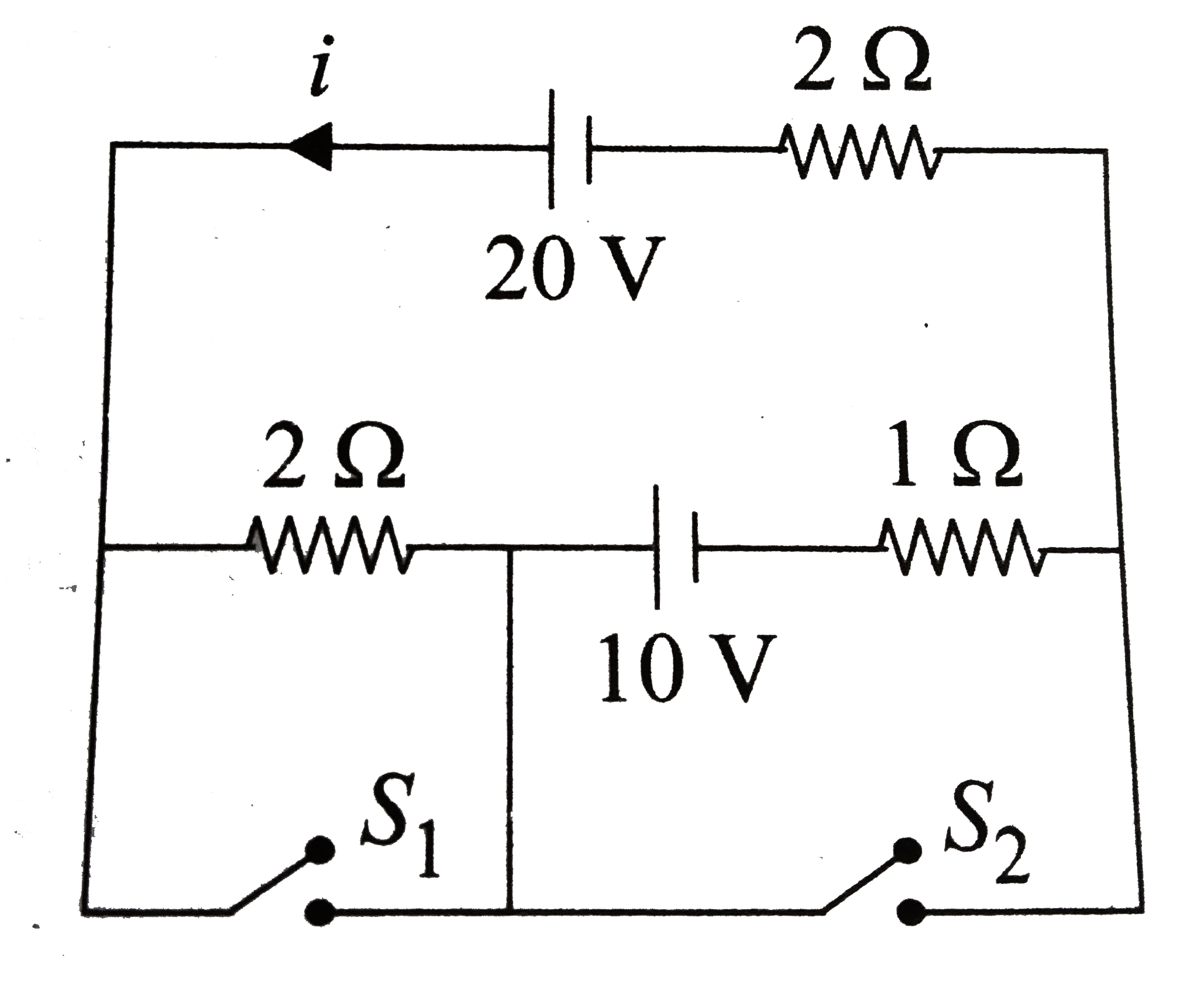
In the circuit shown in figure,
 View Solution
Which one the following statements is ture?
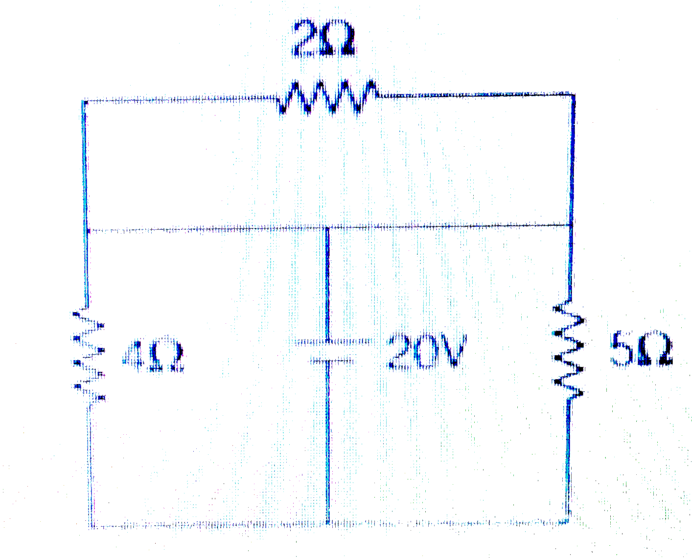
View SolutionIn the circuit shown in figure
 View Solution
In the circuit shown in figure
 View Solution
In the circuit shown in figure
 View Solution
In the circuit shown in figure
 View Solution
In the circuit shown in figure
 View Solution
In the circuit shown in figure
 View Solution
In the circuit shown in figure
 View Solution

