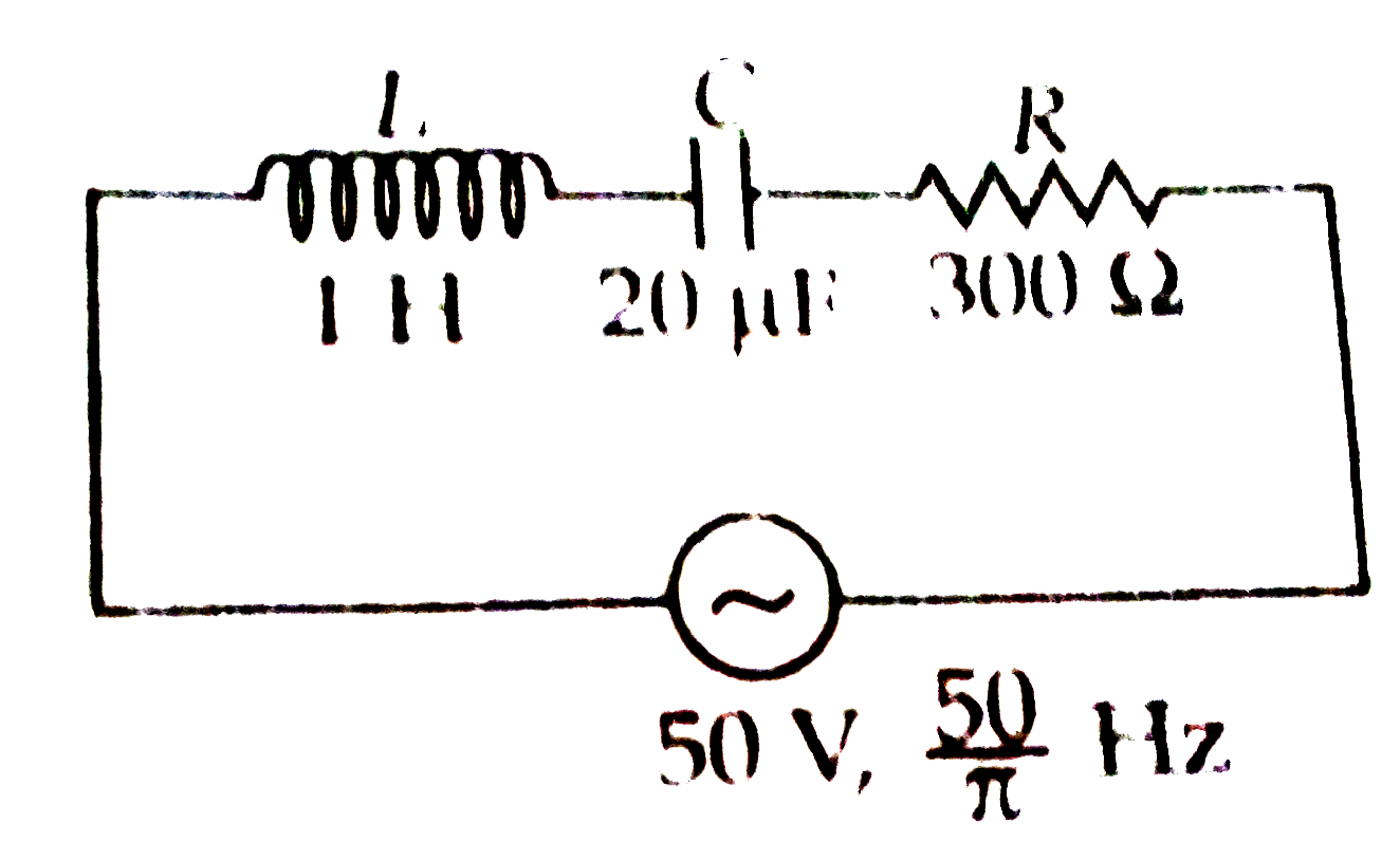
Resonance occures in a series LCR circuit when the frequency of the applied emf is 1000 Hz.
when frequency = 900Hz then the current through the voltage source will be ahead of emf of the source
the impedance of the circuit is minimum at f=1000Hz
at only resonance the voltages across L and C differ in phase by 180∘
if the value of C is double, resonance occurs at f=2000Hz.
The correct Answer is:A, B
To solve the problem regarding resonance in a series LCR circuit, we can follow these steps:
Step 1: Understand the Condition for Resonance
In a series LCR circuit, resonance occurs when the inductive reactance (XL) is equal to the capacitive reactance (XC). Mathematically, this is expressed as:
XL=XC
Step 2: Express Reactances in Terms of Frequency
The inductive reactance (XL) and capacitive reactance (XC) can be expressed as:
XL=ωL=2πfL
XC=1ωC=12πfC
where:
- ω is the angular frequency,
- L is the inductance,
- C is the capacitance,
- f is the frequency of the applied EMF.
Step 3: Set Up the Resonance Condition
At resonance, we set the two reactances equal:
2πfL=12πfC
Step 4: Solve for Frequency
Rearranging the equation gives:
(2πf)2=1LC
Taking the square root of both sides, we find:
2πf=1√LC
Thus, the frequency at resonance is:
f=12π√LC
Step 5: Given Frequency
The problem states that resonance occurs at a frequency of 1000 Hz. Therefore, we can conclude:
f=1000 Hz
Step 6: Analyze the Options
Now, we can analyze the options provided in the question based on the conditions of resonance and the behavior of the circuit:
1. If the frequency is less than 1000 Hz, the circuit becomes capacitive, and the current leads the voltage.
2. If the frequency is equal to 1000 Hz, the impedance is at its minimum and equals the resistance (R).
3. If the frequency is greater than 1000 Hz, the circuit becomes inductive, and the voltage leads the current.
Conclusion
From the analysis:
- Option 1 is correct: At 900 Hz (less than 1000 Hz), the current leads the EMF.
- Option 2 is correct: The impedance is minimum at 1000 Hz (the resonant frequency).
- Option 3 is incorrect: The phase difference between the voltages across L and C is always 180 degrees, not only at resonance.
- Option 4 is incorrect: Doubling the capacitance does not lead to a frequency of 2000 Hz.
Final Answer
The correct options are 1 and 2.
---
In a series LCR circuit, resonance occurs when the inductive reactance (XL) is equal to the capacitive reactance (XC). Mathematically, this is expressed as:
XL=XC
The inductive reactance (XL) and capacitive reactance (XC) can be expressed as:
XL=ωL=2πfL
XC=1ωC=12πfC
where:
- ω is the angular frequency,
- L is the inductance,
- C is the capacitance,
- f is the frequency of the applied EMF.
At resonance, we set the two reactances equal:
2πfL=12πfC
Rearranging the equation gives:
(2πf)2=1LC
Taking the square root of both sides, we find:
2πf=1√LC
Thus, the frequency at resonance is:
f=12π√LC
The problem states that resonance occurs at a frequency of 1000 Hz. Therefore, we can conclude:
f=1000 Hz
Now, we can analyze the options provided in the question based on the conditions of resonance and the behavior of the circuit:
1. If the frequency is less than 1000 Hz, the circuit becomes capacitive, and the current leads the voltage.
2. If the frequency is equal to 1000 Hz, the impedance is at its minimum and equals the resistance (R).
3. If the frequency is greater than 1000 Hz, the circuit becomes inductive, and the voltage leads the current.
From the analysis:
- Option 1 is correct: At 900 Hz (less than 1000 Hz), the current leads the EMF.
- Option 2 is correct: The impedance is minimum at 1000 Hz (the resonant frequency).
- Option 3 is incorrect: The phase difference between the voltages across L and C is always 180 degrees, not only at resonance.
- Option 4 is incorrect: Doubling the capacitance does not lead to a frequency of 2000 Hz.
The correct options are 1 and 2.
Topper's Solved these Questions
- BOOK - CENGAGE PHYSICS ENGLISHCHAPTER - ALTERNATING CURRENTEXERCISE - Exercises Assertion-reasoning7videos
ALTERNATING CURRENT
- BOOK - CENGAGE PHYSICS ENGLISHCHAPTER - ALTERNATING CURRENTEXERCISE - Exercises Linked Comprehension25videos
ALTERNATING CURRENT
- BOOK - CENGAGE PHYSICS ENGLISHCHAPTER - ALTERNATING CURRENTEXERCISE - Exercises Single Correct63videos
ALTERNATING CURRENT
- BOOK - CENGAGE PHYSICS ENGLISHCHAPTER - ATOMIC PHYSICSEXERCISE - ddp.4.315videos
ATOMIC PHYSICS
Similar Questions
Knowledge Check
- Question 1 - Select One
In the series LCR circuit shown the impedance is
 A200ΩB100ΩC300ΩD500Ω
The power factor of a series LCR circuit is
View SolutionDraw a labelled graph showing variation of impedance of a series LCR circuit with frequency of the a.c. supply.
View SolutionAn alternating EMF of frequency 12π√LC is applied to a series LCR circuit. For this frequency of the applied EMF,
View SolutionPower factor in series LCR circuit at reasonance is
View SolutionIn LCR circuit during resonance
View SolutionThe series RLC circuit in resonance is called:
View SolutionIn a series LCR circuit, at resonance, power factor is …….. .
View Solution

