A potential divider is used to give outpurs of 4V and 8V from a 12V source. Which combination of resistance, (R1,R2,R3 gives the correct voltages? (R_(1) : R_(2) : R_(3)
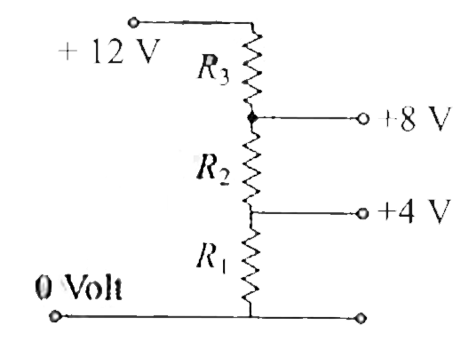
2:1:2
1:1:1
2:2:1
1:1:2
The correct Answer is:B
Step by step video & image solution for A potential divider is used to give outpurs of 4V and 8V from a 12V source. Which combination of resistance, (R_(1), R_(2), R_(3) gives the correct voltages? (R_(1) : R_(2) : R_(3) by Physics experts to help you in doubts & scoring excellent marks in Class 12 exams.
Updated on:21/07/2023Topper's Solved these Questions
- ELECTRIC CURRENT & CIRCUITSBOOK - CENGAGE PHYSICS ENGLISHCHAPTER - ELECTRIC CURRENT & CIRCUITSEXERCISE - Kirchhoff s Law and Grouping Cells
15 Videos
- ELECTRIC CURRENT & CIRCUITSBOOK - CENGAGE PHYSICS ENGLISHCHAPTER - ELECTRIC CURRENT & CIRCUITSEXERCISE - Kirchhoff s law and simple circuits
15 Videos
- ELECTRIC CURRENT & CIRCUITSBOOK - CENGAGE PHYSICS ENGLISHCHAPTER - ELECTRIC CURRENT & CIRCUITSEXERCISE - Combination of Resistance 1
14 Videos
- COULOMB LAW AND ELECTRIC FIELDBOOK - CENGAGE PHYSICS ENGLISHCHAPTER - COULOMB LAW AND ELECTRIC FIELDEXERCISE - Single Answer Correct Type
22 Videos
- ELECTRIC CURRENT AND CIRCUITBOOK - CENGAGE PHYSICS ENGLISHCHAPTER - ELECTRIC CURRENT AND CIRCUITEXERCISE - Interger
8 Videos
Similar Questions
A potential divider is used to given outputs of 2V and 3V form a 5V source, as shown in fig.
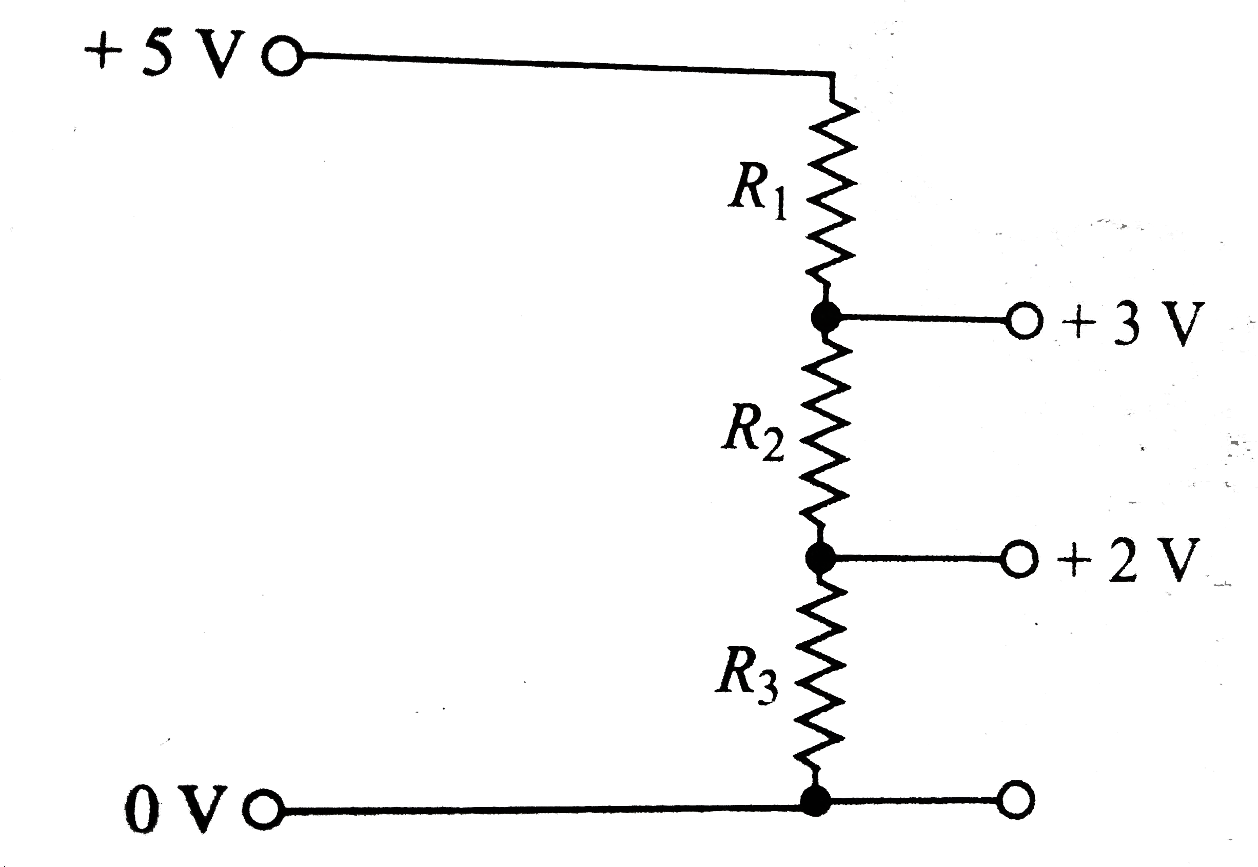
Which combination of resistance R1,R2,andR3 gives the correct voltages?
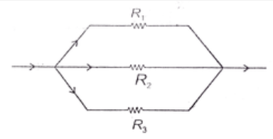
View SolutionIn the situation shown, resistance R1,R2 and R3 are in the ratio 3:2:1 , then
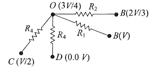
View SolutionThe circuit is shown in the following figure. The potential at points A, B, C, D and O are given. The currents in the resistance R1,R2 and R3 are in the ratio of 4:2:1. What is the ratio of resistance R1,R2,R3 and R4 ?
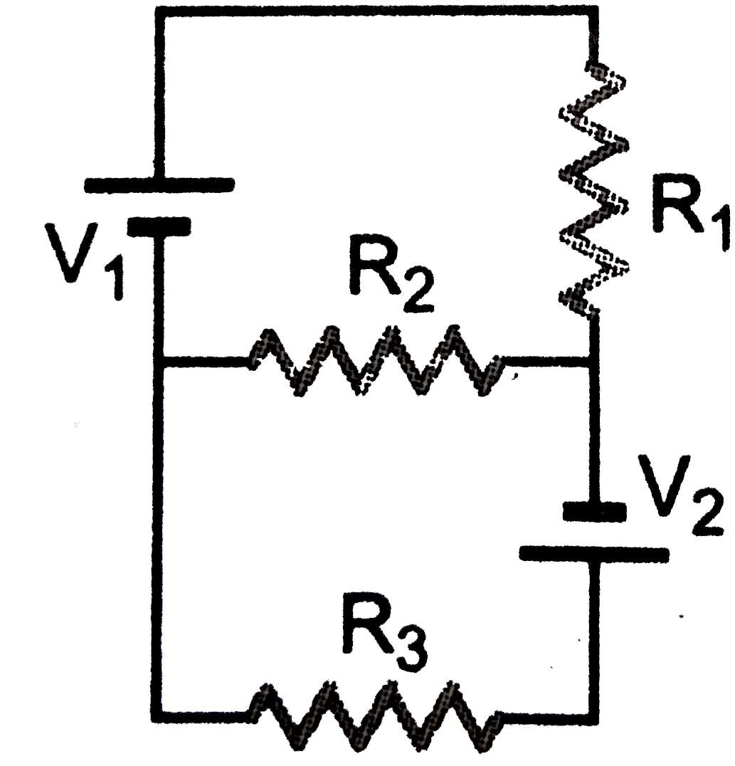
View SolutionTwo ideal batteries of emfV1andV2 and three resistance R1R2andR3 are connected The current in resistance R2 would be zero if
View SolutionA resistance R1 is connected to a source of constant voltage . On connecting a resistance R2 in series with R1
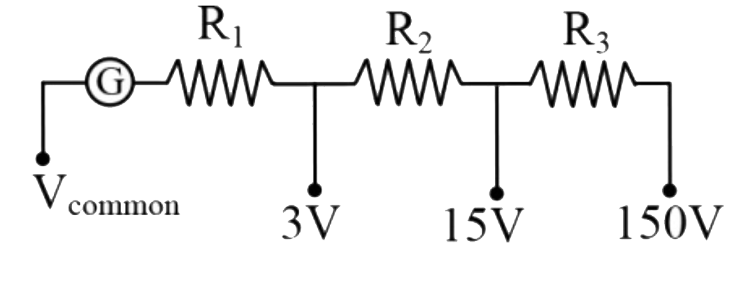
View SolutionA voltmeter of variable ranges 3V, 15V, 150 V is to designed by connecting resistances R1,R2,R3 in series with a galvanometer of resistance G=20Ω, as shown in the figure. The galvanometer gives full pass through its coil. Then, the resistances R1,R2andR3 (in kilo ohms) should be, respectively
View SolutionA capacitor of capacitance C, charged to a potential difference V, is discharged through a series combination of two resistors R1 and R2. Find the heat generated in resistor R1 during discharging.
View SolutionFor a cell, the terminal potential difference is 2.2V, when circuit is open and reduces to 1.8V. When cell is connected to a resistance R=5Ω, the internal resistance of cell (R) is
View SolutionFor a cell, the terminal potential difference is 2.2V, when circuit is open and reduces to 1.8V. When cell is connected to a resistance R=5Ω, the internal resistance of cell (R) is
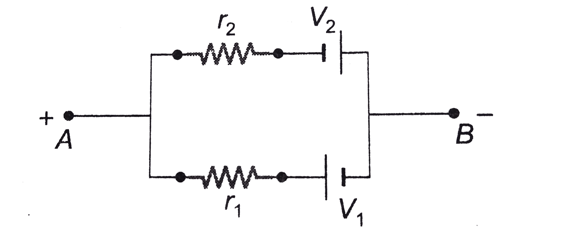
View SolutionFind the emf (V) and internal resistance (R) of a single battery which is equivalent toa parallel combination of two batteries of emf V1 and V2 and internal resistances r1 and r2 respectively, with polrities as shown in figure
View Solution
