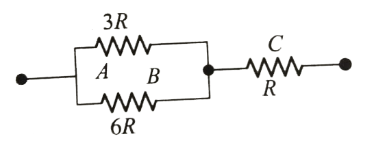
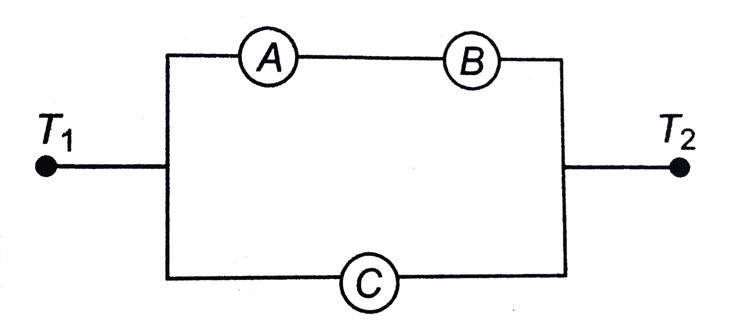
Figure 7.37 shows a network of three resistances. When some potential difference is applied across the network , thermal powers dissipated by A,BandC are in the ratio
2:3:4
2:4:3
4:2:3
3:2:4
The correct Answer is:C
Step by step video & image solution for Figure 7.37 shows a network of three resistances. When some potential difference is applied across the network , thermal powers dissipated by A, B and C are in the ratio by Physics experts to help you in doubts & scoring excellent marks in Class 12 exams.
Updated on:21/07/2023Topper's Solved these Questions
- HEATING EFFECT OF CURRENTBOOK - CENGAGE PHYSICS ENGLISHCHAPTER - HEATING EFFECT OF CURRENTEXERCISE - Calculating Thermal Power in Resistance
14 Videos
- GEOMETRICAL OPTICSBOOK - CENGAGE PHYSICS ENGLISHCHAPTER - GEOMETRICAL OPTICSEXERCISE - Integer Type
4 Videos
- INDUCTANCEBOOK - CENGAGE PHYSICS ENGLISHCHAPTER - INDUCTANCEEXERCISE - Concept Based
8 Videos
Similar Questions
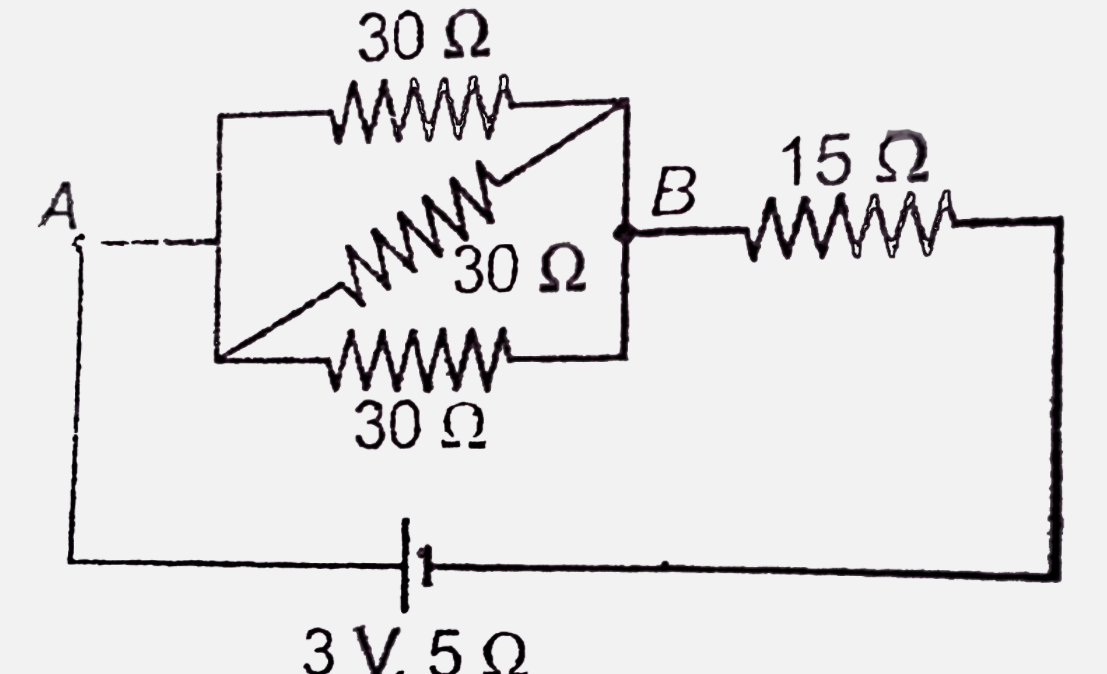
Potential difference across AB in the network shown in figure.
View SolutionThree identical resistors are connected in series . When a certain potential difference is applied across the combination , the total power would be dissipated is 27W. How many times the power would be dissipated if the three resistors were connected in parallel across the same potential difference ?
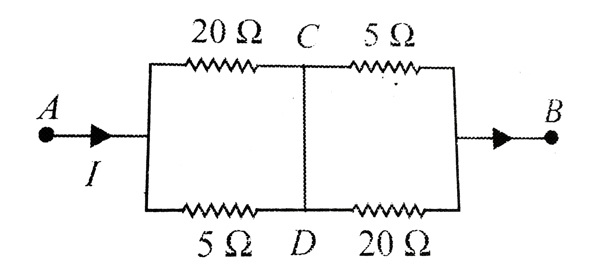
View SolutionWhen some potential differece is maintained between A and B, current I enters the network at A and leaves at B
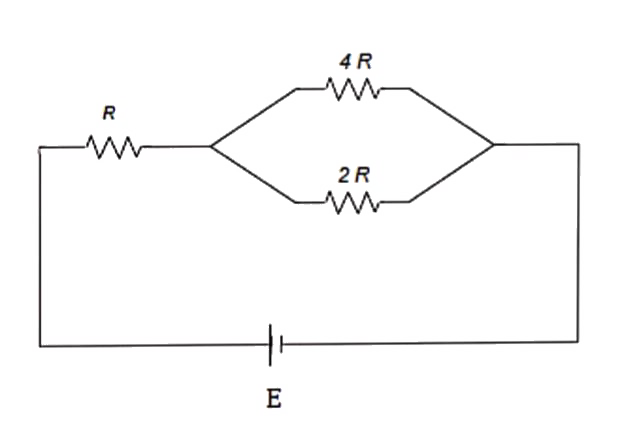
View SolutionThe figure shows a network in which the cell is deal and it has an emf E. The potential difference across the resistance 2R is
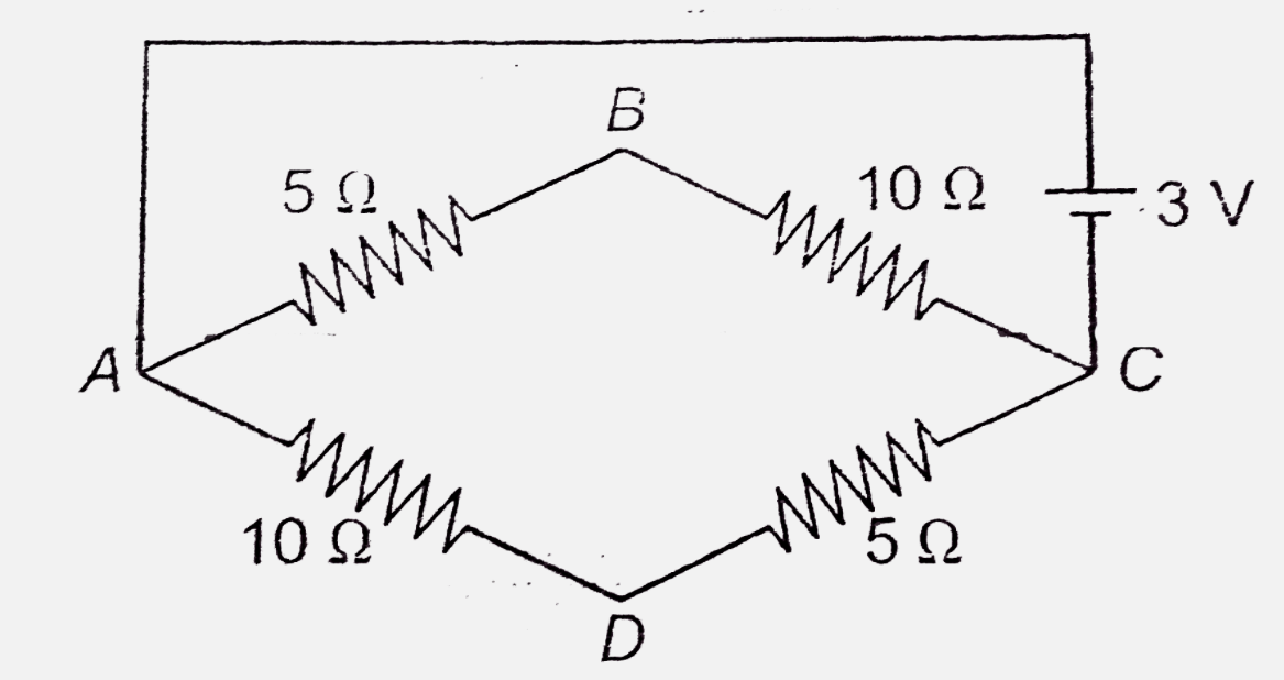
View SolutionIn the network shown in given figure, find the potential difference across BD
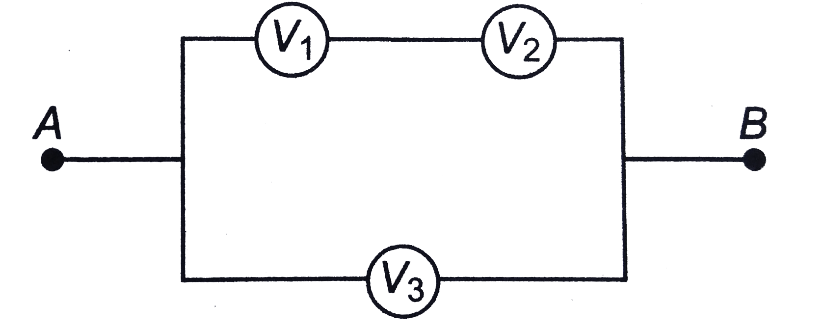
View SolutionThree voltmeters all having different resistance, are joined as shown. When some potential difference is applied acros A and B, their readings are V1,V2 and V3. Then
View SolutionIn the circuit shown some potential difference is applied between A and B. The equivalent resistance between A and B is R. Then
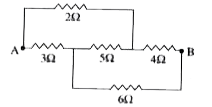
View SolutionIn the circuit shown in fig. some potential difference is applied between A and B. The equivalent resistance between A and B is R.

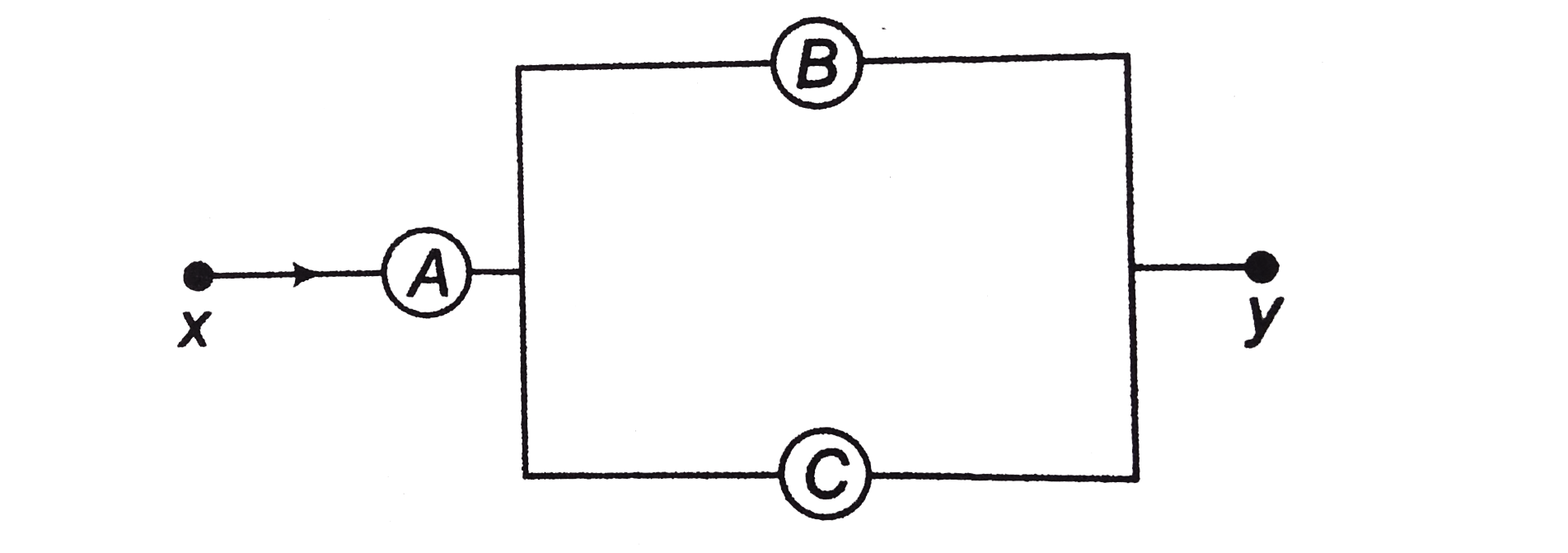
View SolutionA,B and C are voltmeters of resistances R,1.5R and 3R respectively. When some potential difference is applied between x and y the voltmeter readings are VA,VBandVC, then
View SolutionThree ammeters A,B, and C of resistances RA,Rb and RC respectively are joined as shown. When some potential difference is appllied across the terminals T1 and T2 their readings are IA,IBandIC respectively Then,
View Solution