Which circuit will not show current in ammeter ?

The correct Answer is:A
To determine which circuit will not show current in the ammeter, we need to analyze each circuit option provided. Let's go through the steps systematically.
1. Understanding the Circuit Components: Recognize that diodes have two terminals: anode and cathode. A diode allows current to flow in one direction (forward bias) and blocks it in the opposite direction (reverse bias).
2. Analyzing Option 1:
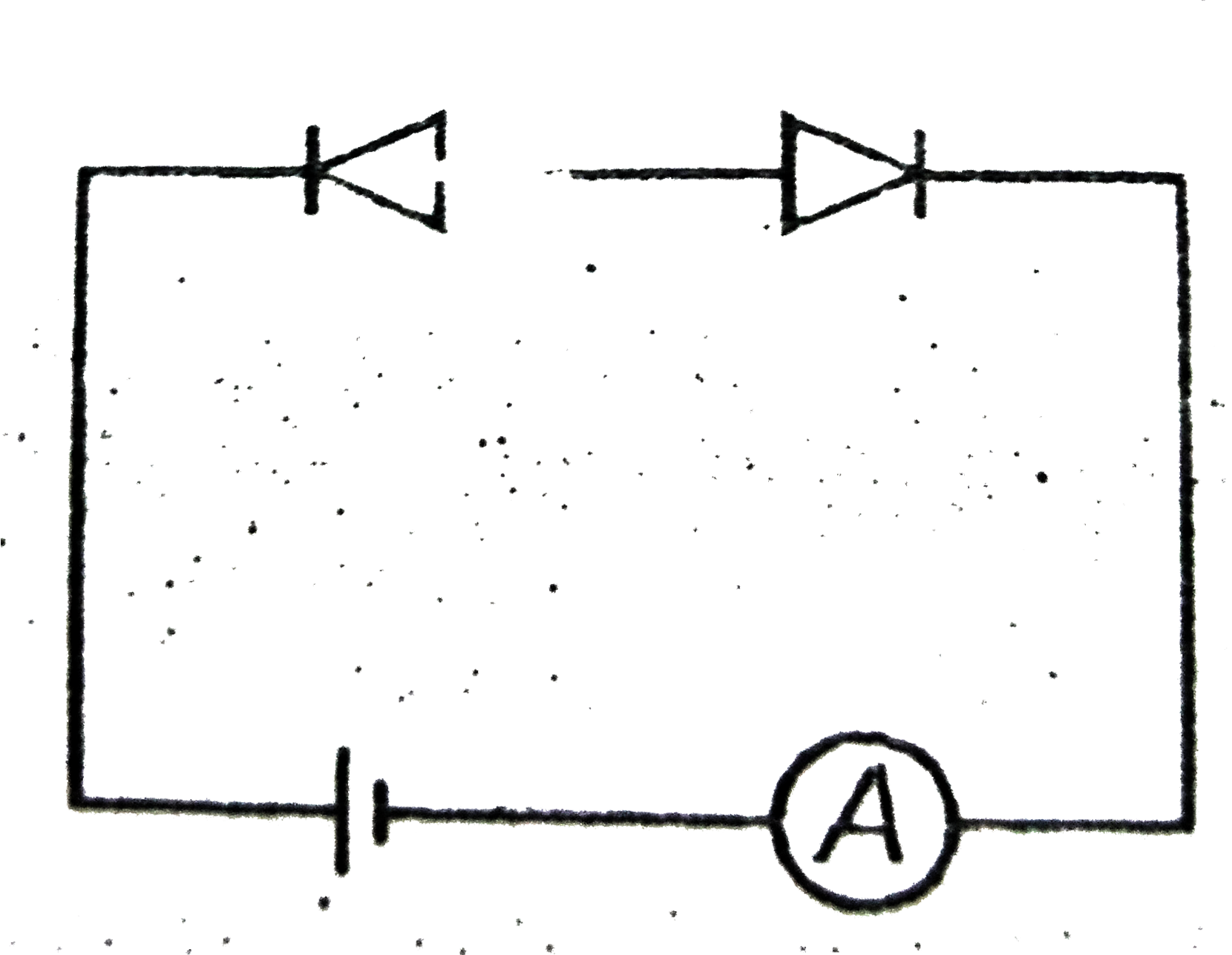
- In this circuit, we have two diodes connected in series.
- The first diode is reverse biased (anode connected to the negative terminal and cathode to the positive terminal).
- The second diode is forward biased (anode connected to the positive terminal and cathode to the negative terminal).
- Since one diode is reverse biased, it will not allow current to flow through the circuit, making it an open circuit.
- Conclusion for Option 1: No current flows; hence, the ammeter will show zero current.
3. Analyzing Option 2:
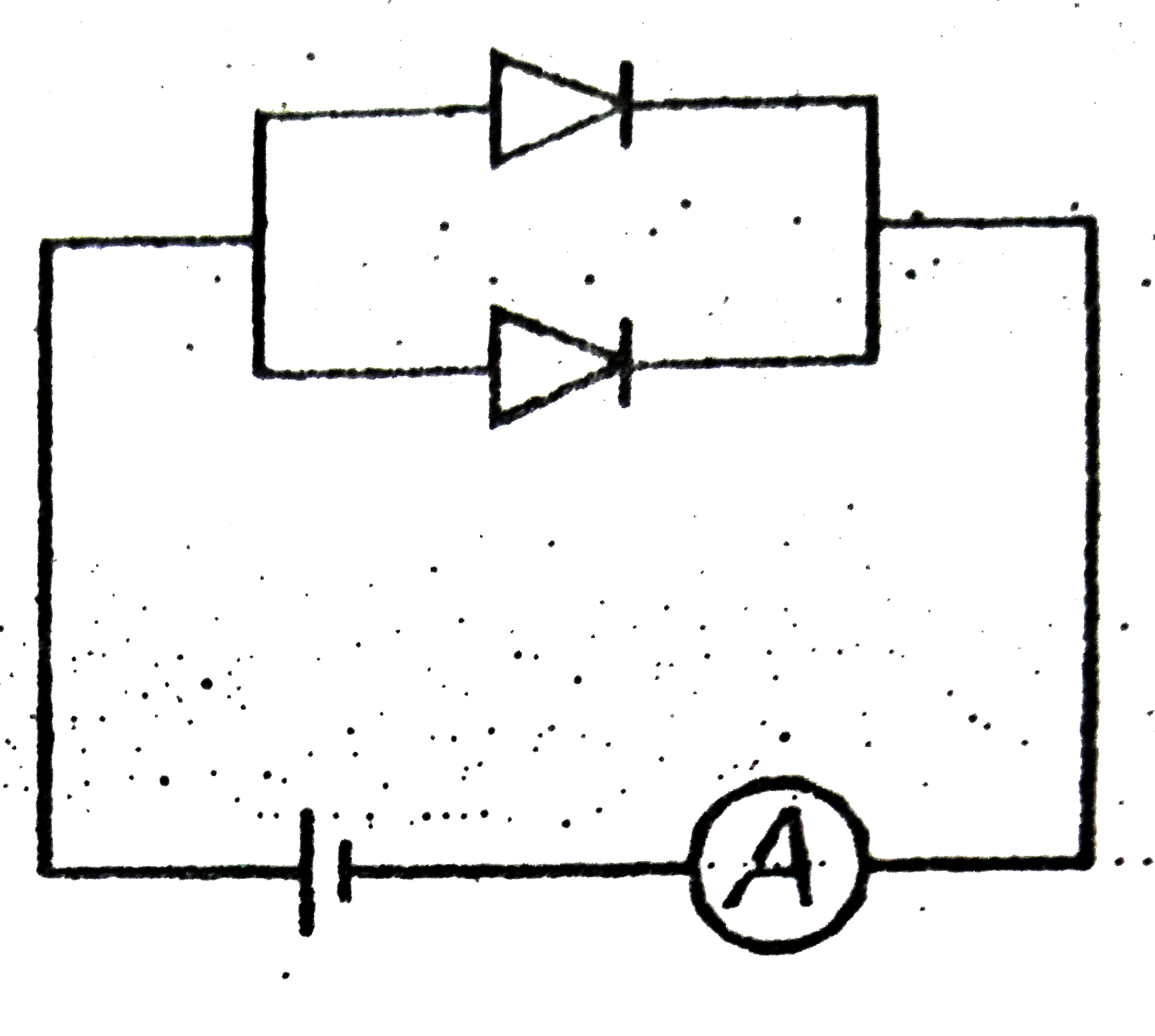
- This circuit has two diodes connected in series, both in forward bias.
- Both diodes will conduct electricity as they are oriented correctly.
- Conclusion for Option 2: Current will flow; the ammeter will show current.
4. Analyzing Option 3:
- Here, two diodes are connected in parallel, both with the same polarity.
- Both diodes are forward biased and will conduct electricity.
- Conclusion for Option 3: Current will flow; the ammeter will show current.
5. Analyzing Option 4:
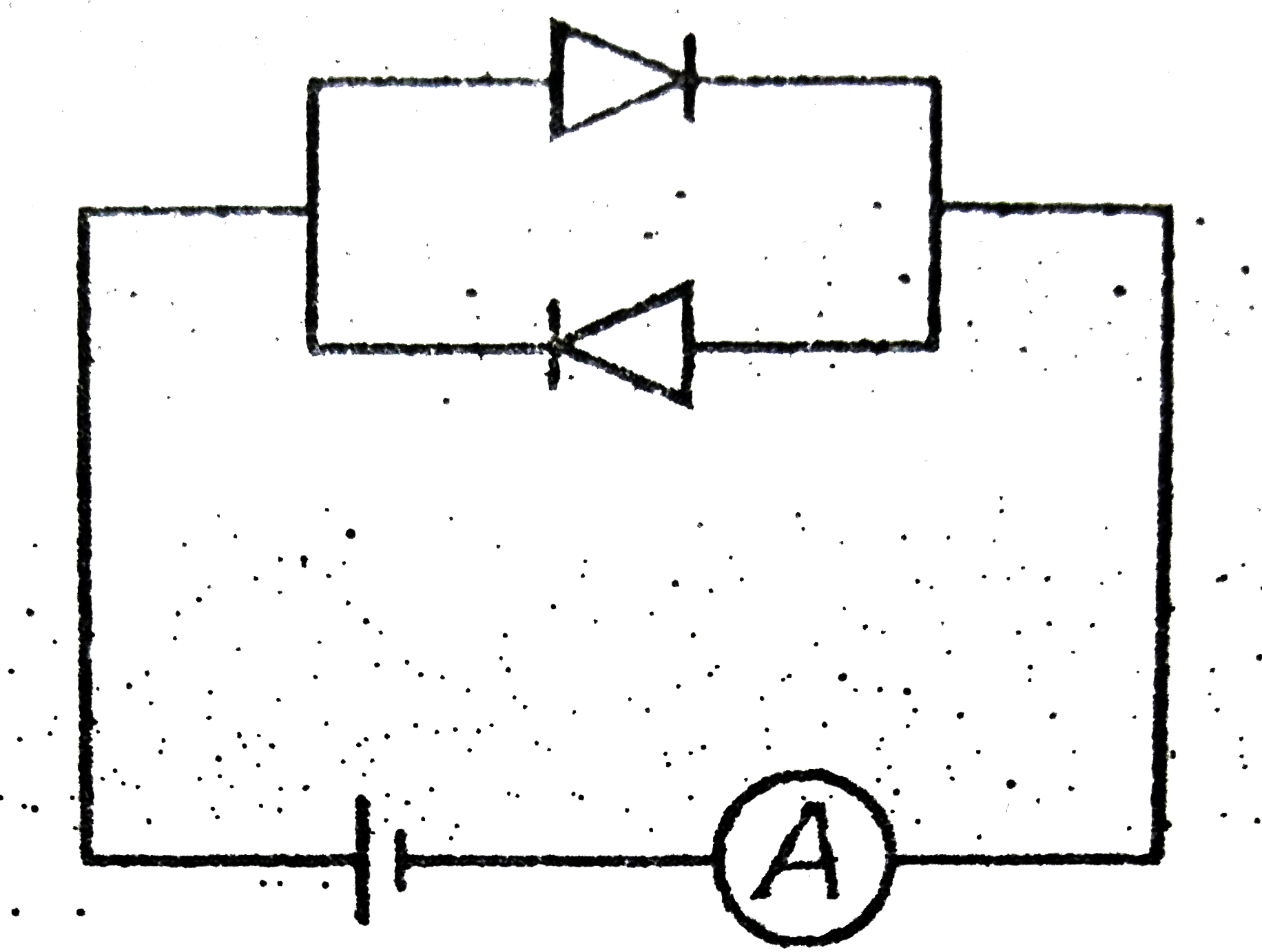
- In this circuit, two diodes are connected in series but with opposite polarities.
- One diode is forward biased while the other is reverse biased.
- The forward biased diode will conduct, while the reverse biased diode will block current.
- Conclusion for Option 4: Current will flow through the forward biased diode; the ammeter will show current.
6. Final Conclusion: After analyzing all options, only Option 1 does not allow current to flow due to the reverse bias of one of the diodes. Therefore, the circuit that will not show current in the ammeter is Option 1.
Final Answer:
Option 1 is the correct answer; it will not show current in the ammeter.
- In this circuit, we have two diodes connected in series.
- The first diode is reverse biased (anode connected to the negative terminal and cathode to the positive terminal).
- The second diode is forward biased (anode connected to the positive terminal and cathode to the negative terminal).
- Since one diode is reverse biased, it will not allow current to flow through the circuit, making it an open circuit.
- Conclusion for Option 1: No current flows; hence, the ammeter will show zero current.
- This circuit has two diodes connected in series, both in forward bias.
- Both diodes will conduct electricity as they are oriented correctly.
- Conclusion for Option 2: Current will flow; the ammeter will show current.
- Here, two diodes are connected in parallel, both with the same polarity.
- Both diodes are forward biased and will conduct electricity.
- Conclusion for Option 3: Current will flow; the ammeter will show current.
- In this circuit, two diodes are connected in series but with opposite polarities.
- One diode is forward biased while the other is reverse biased.
- The forward biased diode will conduct, while the reverse biased diode will block current.
- Conclusion for Option 4: Current will flow through the forward biased diode; the ammeter will show current.
Option 1 is the correct answer; it will not show current in the ammeter.
Topper's Solved these Questions
- SEMICONDUCTOR ELECTRONICS: MATERIALS, DEVICES AND SIMPLE CIRCUITSBook:AAKASH INSTITUTE ENGLISHChapter:SEMICONDUCTOR ELECTRONICS: MATERIALS, DEVICES AND SIMPLE CIRCUITSExercise:Assignment (Section -B (Objective type question (one option is correct))
Explore 29 Videos
- SEMICONDUCTOR ELECTRONICS: MATERIALS, DEVICES AND SIMPLE CIRCUITSBook:AAKASH INSTITUTE ENGLISHChapter:SEMICONDUCTOR ELECTRONICS: MATERIALS, DEVICES AND SIMPLE CIRCUITSExercise:Assignment (Section -C(Linked comprehension type question))
Explore 3 Videos
- SEMICONDUCTOR ELECTRONICS: MATERIALS, DEVICES AND SIMPLE CIRCUITSBook:AAKASH INSTITUTE ENGLISHChapter:SEMICONDUCTOR ELECTRONICS: MATERIALS, DEVICES AND SIMPLE CIRCUITSExercise:Try yourself
Explore 20 Videos
- SEMICONDUCTOR ELECTRONICS (MATERIAL, DEVICES AND SIMPLE CIRUITS )Book:AAKASH INSTITUTE ENGLISHChapter:SEMICONDUCTOR ELECTRONICS (MATERIAL, DEVICES AND SIMPLE CIRUITS )Exercise:Assignment SECTION - D (Assertion & reason type Question)
Explore 10 Videos
- SYSTEM OF PARTICLES AND ROTATIONAL MOTIONBook:AAKASH INSTITUTE ENGLISHChapter:SYSTEM OF PARTICLES AND ROTATIONAL MOTIONExercise:Try Yourself
Explore 63 Videos
Similar Questions
Consider a circular as shows in Fig. 6.5 (a). We want to measure the current i flowing in the circuit.
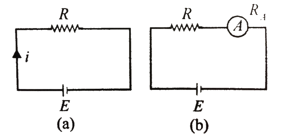
For this we connect an ammeter of resistance RA as shows in Fig. 6.5(b). Find the percentage error in the current.
View SolutionIn the circuit shown in figure, reading of ammeter will
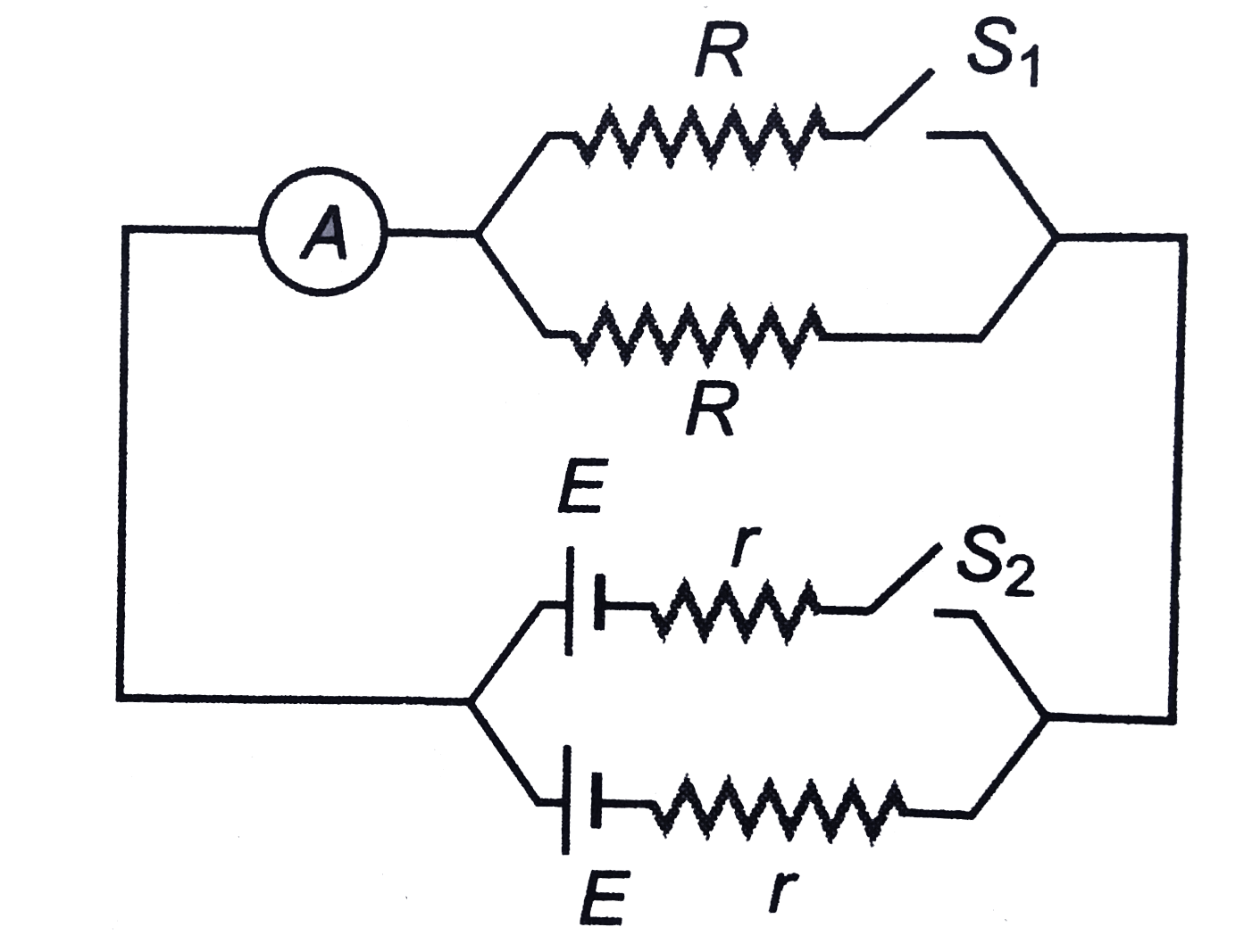
View SolutionIn the circuit shown in figure, the current is to measured. What is the value of the current if the ammeter shown (i) is a galvanometer with a resistance RG=60⋅00Ω. (ii) is a galvanometer described in (i) but converted to an ammeter by a shunt resistance rs=0⋅02Ω, (iii) is an ideal ammeter with zero resistance?
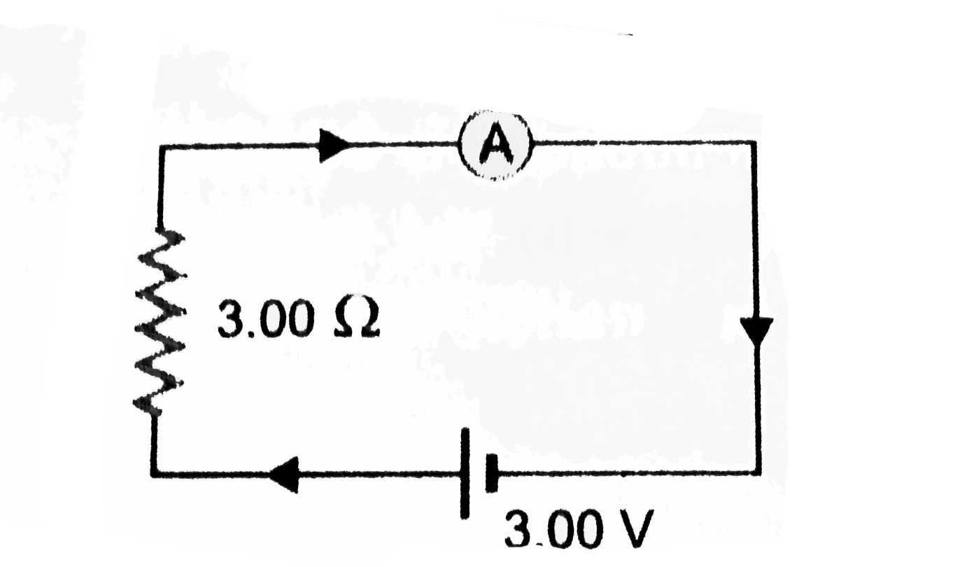
View SolutionIn the circuit shown in figure the reading of ammeter is the same with both switches open as with both closed. Then find the resistance R. (ammeter is ideal).
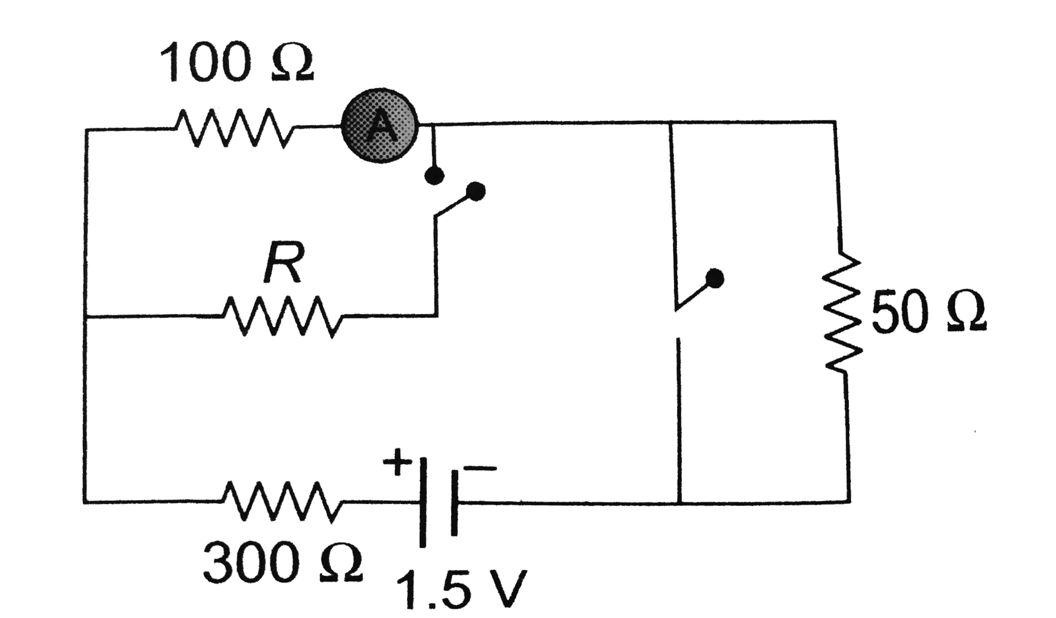
View SolutionIn the circuit shown in figure the reading of ammeter is the same with both switches open as with both closed. Then find the resistance R. (ammeter is ideal).

View SolutionThe figure shows a circuit.
When the circuit is switched on, the ammeter reads 0.5A.
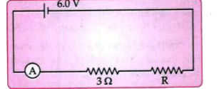
Calculate the power dissipated in the 3Ω resistor.
View SolutionThe figure shows a circuit.
When the circuit is switched on, the ammeter reads 0.5A.
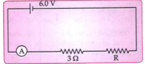
Calculate the value of the unknown resistor R.
View SolutionThe figure shows a circuit.
When the circuit is switched on, the ammeter reads 0.5A.
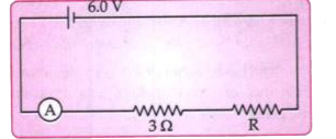
Calculate the charge passing through the 3Ω resistor in 120 s.
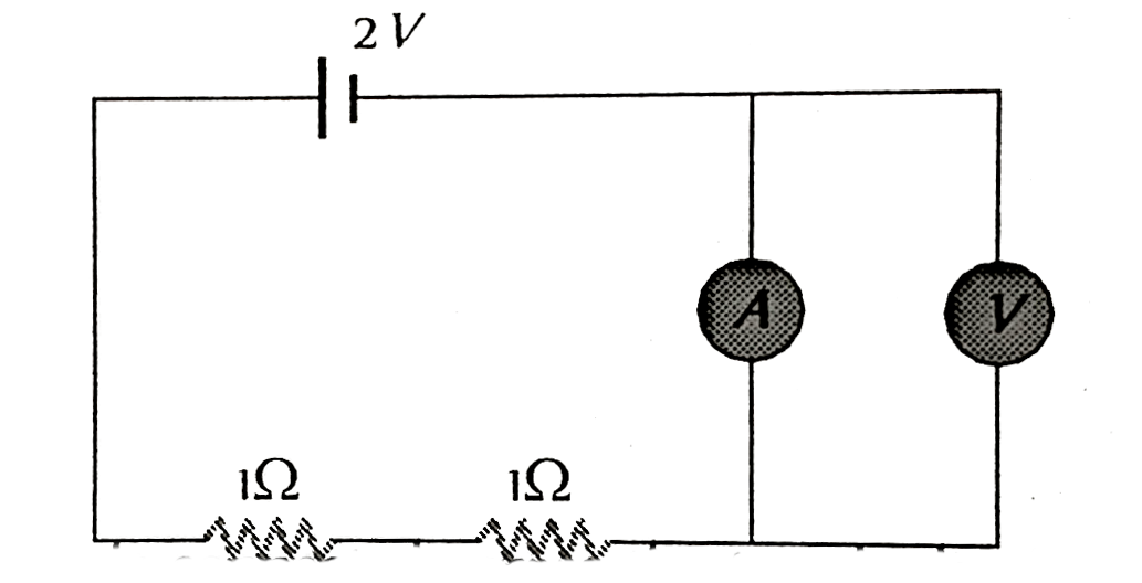
View SolutionIn the circuit shown, A and V are ideal ammeter and voltmeter respectively. Reading of the voltmeter will be
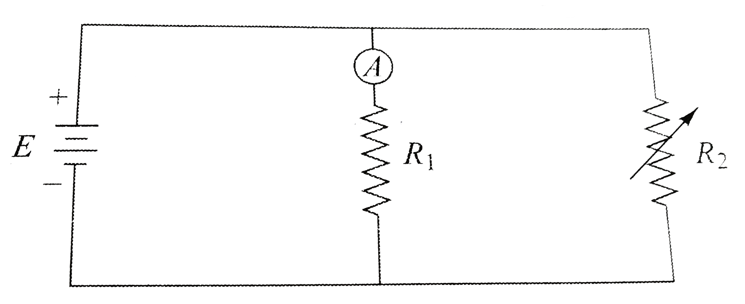
View SolutionIn the given circuit in which case will the ammeter reading not change when R2 is varied?
View Solution