Figure shows the circuit of a flashing lamp, used at construction sites. The fluorescent lamp L, having negligible capacitance, is connected in parallel across the capacitor C of an RC circuit . There is a current through the lamp only when the potential difference across it reaches the breakdown voltage V1). In this event, the capacitor discharges completley through the lamp and lamp flashes momentarily.
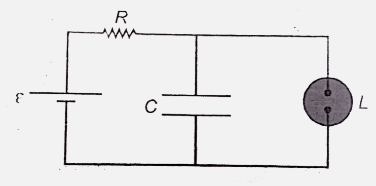
Which of the following graphs represents the variation fo potential drop across the resistor ?
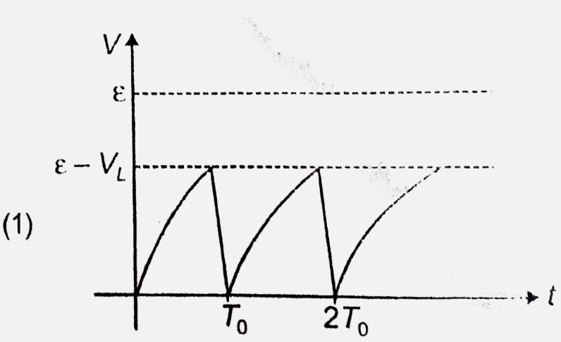
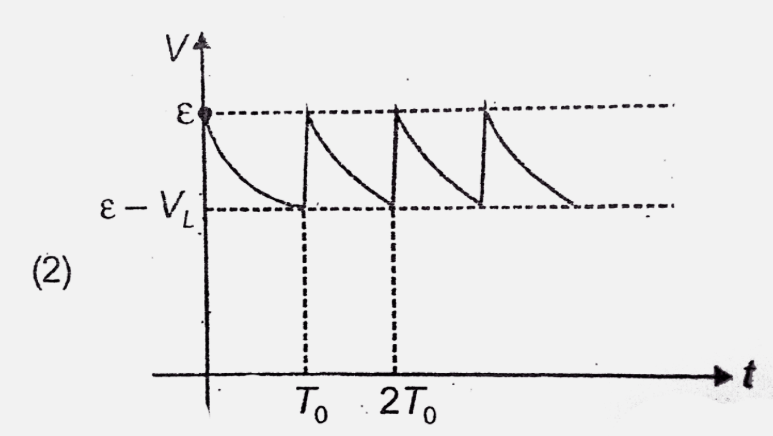
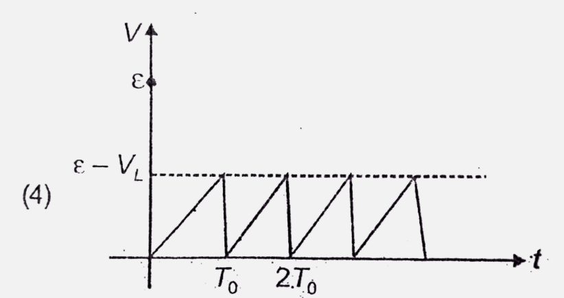
The correct Answer is:2
Step by step video & image solution for Figure shows the circuit of a flashing lamp, used at construction sites. The fluorescent lamp L, having negligible capacitance, is connected in parallel across the capacitor C of an RC circuit . There is a current through the lamp only when the potential difference across it reaches the breakdown voltage V_1). In this event, the capacitor discharges completley through the lamp and lamp flashes momentarily. Which of the following graphs represents the variation fo potential drop across the resistor ? by Physics experts to help you in doubts & scoring excellent marks in Class 12 exams.
Updated on:21/07/2023Topper's Solved these Questions
- CURRENT ELECTRICITYBOOK - AAKASH INSTITUTE ENGLISHCHAPTER - CURRENT ELECTRICITYEXERCISE - ASSIGNMENT SECTION-D( LINKED COMPREHENSION TYPE QUESTIONS) Comprehension - II
5 Videos
- CURRENT ELECTRICITYBOOK - AAKASH INSTITUTE ENGLISHCHAPTER - CURRENT ELECTRICITYEXERCISE - ASSIGNMENT SECTION-E (ASSERTION-REASON TYPE QUESTION)
15 Videos
- CURRENT ELECTRICITYBOOK - AAKASH INSTITUTE ENGLISHCHAPTER - CURRENT ELECTRICITYEXERCISE - ASSIGNMENT SECTION-C(OBJECTIVE TYPE QUESTION ))
13 Videos
- COMMUNICATION SYSTEMS BOOK - AAKASH INSTITUTE ENGLISHCHAPTER - COMMUNICATION SYSTEMS EXERCISE - ASSIGNMENT SECTION D (Assertion-Reason)
10 Videos
- DUAL NATURE OF RADIATION AND MATTER BOOK - AAKASH INSTITUTE ENGLISHCHAPTER - DUAL NATURE OF RADIATION AND MATTER EXERCISE - ASSIGNMENT (SECTION-D)
10 Videos
Similar Questions
Figure shows the circuit of a flashing lamp, used at construction sites. The fluorescent lamp L, having negligible capacitance, is connected in parallel across the capacitor C of an RC circuit . There is a current through the lamp only when the potential difference across it reaches the breakdown voltage V1). In this event, the capacitor discharges completley through the lamp and lamp flashes momentarily.
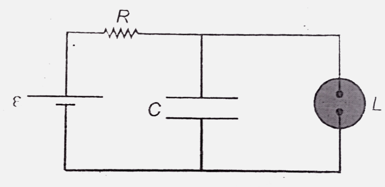
The number of flashes per second produced by the arrangement is ( neglecting th etime of flashing or discharging of capacitor)
View SolutionFigure shows the circuit of a flashing lamp, used at construction sites. The fluorescent lamp L, having negligible capacitance, is connected in parallel across the capacitor C of an RC circuit . There is a current through the lamp only when the potential difference across it reaches the breakdown voltage VL). In this event, the capacitor discharges completley through the lamp and lamp flashes momentarily.
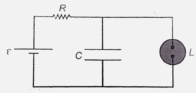
Consider an instant, when the capacitor has just discharged through the flash light. Taking this instant as t=0, the time after which the lamp flashes momentarily is given by
View Solution
Knowledge Check
A capacitor or capacitance C1 is charge to a potential V and then connected in parallel to an uncharged capacitor of capacitance C2. The fianl potential difference across each capacitor will be
AC1VC1+C2BC2VC1+C2C1+C2C1D1−C2C1
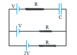
In the given circuit, with steady current, the potential difference across the capacitor is
View SolutionIn the circuit shown in the figure, the potential difference across the 4.5μF capacitor is
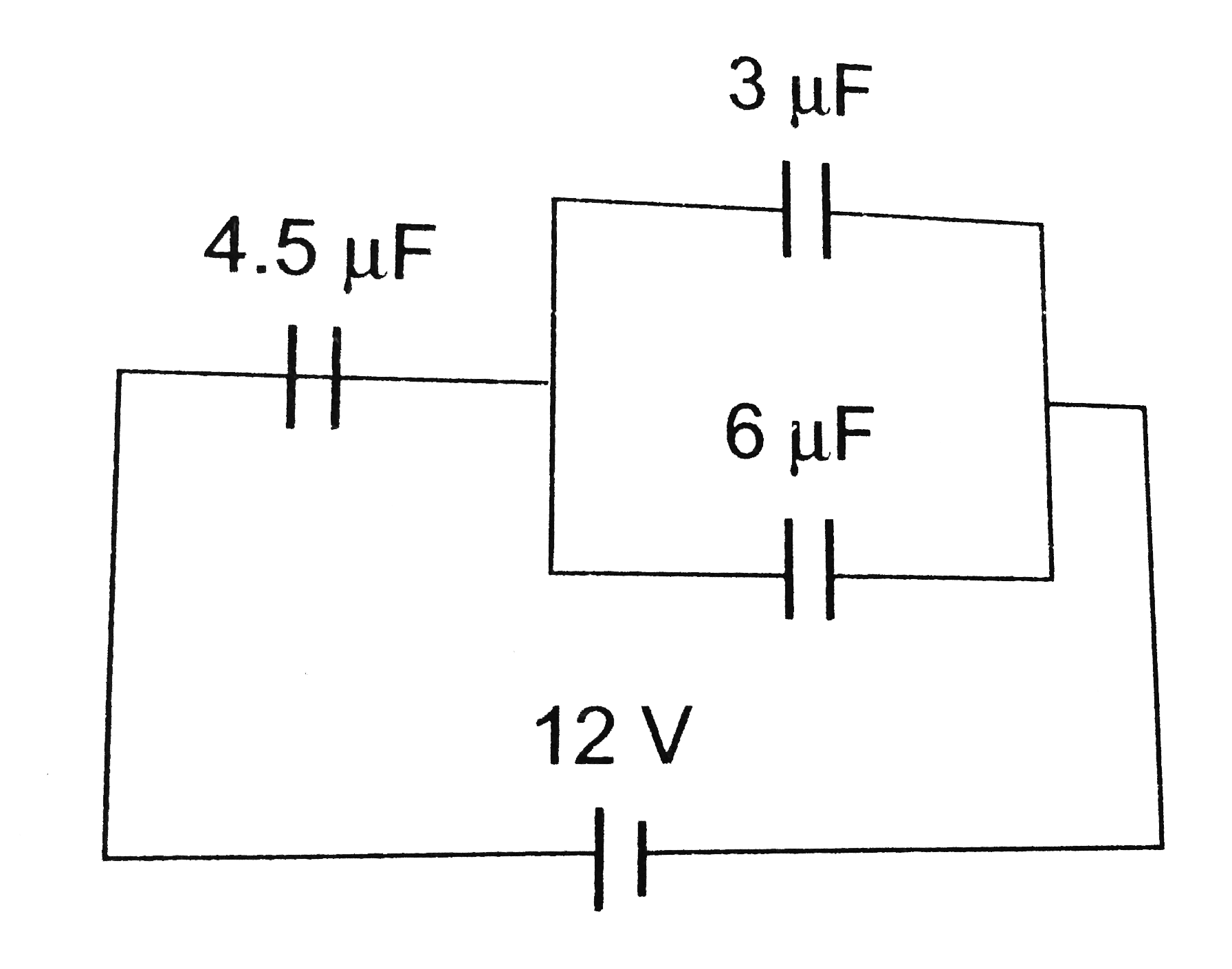
View SolutionIn the circuit shown in figure find

a. the equivalent capacitance
b. the charge stored in each capacitor and
c. the potential difference across each capacitor.
View SolutionA capacitor of capacity 2μF is changed to a potential different of 12V . It is then connected across an inductor of inductance 0.6mH What is the current in the circuit at a time when the potential difference across the capacitor is 6.0V ?
View SolutionA capacitor of capacity 2μF is changed to a potential different of 12V . It is then connected across an inductor of inductance 0.6mH What is the current in the circuit at a time when the potential difference across the capacitor is 6.0V ?
View SolutionThe spirit lamp is made of
View SolutionA capacitor is connected to a 12 V battery through a resistance of (10Ω).It is found that the potential difference across the capacitor rises to 4.0 V in 1(mu)s. find the capacitance of the capacitor.
View Solution
