A copper rod of length l is rotated about one end perpendicular to the uniform magnetic field B with constant angular velocity ω . The induced e.m.f. between its two ends is
Bωl2
32Bωl2
12Bωl2
2Bωl2
The correct Answer is:C
To find the induced electromotive force (e.m.f.) between the two ends of a rotating copper rod in a magnetic field, we can follow these steps:
Step 1: Understand the Setup
We have a copper rod of length L that is rotating about one of its ends with a constant angular velocity ω. The magnetic field B is uniform and perpendicular to the plane of rotation of the rod.
Step 2: Determine the Linear Velocity
The linear velocity v of a point on the rod at a distance r from the pivot (the end about which it is rotating) is given by:
v=ωr
For a point at the end of the rod, r=L, so:
v=ωL
Step 3: Calculate the Velocity at the Midpoint
To find the average velocity of the rod, we can consider the midpoint of the rod, which is at r=L2:
vmid=ω(L2)=ωL2
Step 4: Use the Formula for Induced EMF
The induced e.m.f. E can be calculated using the formula:
E=v⋅B⋅L
Since v is the average velocity of the rod, we substitute vmid:
E=(ωL2)⋅B⋅L
Step 5: Simplify the Expression
Now, simplifying the expression:
E=ωL2⋅B⋅L=12BωL2
Final Answer
Thus, the induced e.m.f. between the two ends of the rod is:
E=12BωL2
We have a copper rod of length L that is rotating about one of its ends with a constant angular velocity ω. The magnetic field B is uniform and perpendicular to the plane of rotation of the rod.
The linear velocity v of a point on the rod at a distance r from the pivot (the end about which it is rotating) is given by:
v=ωr
For a point at the end of the rod, r=L, so:
v=ωL
To find the average velocity of the rod, we can consider the midpoint of the rod, which is at r=L2:
vmid=ω(L2)=ωL2
The induced e.m.f. E can be calculated using the formula:
E=v⋅B⋅L
Since v is the average velocity of the rod, we substitute vmid:
E=(ωL2)⋅B⋅L
Now, simplifying the expression:
E=ωL2⋅B⋅L=12BωL2
Thus, the induced e.m.f. between the two ends of the rod is:
E=12BωL2
Topper's Solved these Questions
- ELECTROMAGNETIC INDUCTIONBOOK - AAKASH INSTITUTE ENGLISHCHAPTER - ELECTROMAGNETIC INDUCTIONEXERCISE - ASSIGNMENT(SECTION - B) (OBJECTIVE TYPE QUESTIONS)
25 Videos
- ELECTROMAGNETIC INDUCTIONBOOK - AAKASH INSTITUTE ENGLISHCHAPTER - ELECTROMAGNETIC INDUCTIONEXERCISE - ASSIGNMENT(SECTION -C) Previous Years Questions
34 Videos
- ELECTROMAGNETIC INDUCTIONBOOK - AAKASH INSTITUTE ENGLISHCHAPTER - ELECTROMAGNETIC INDUCTIONEXERCISE - EXERCISE
30 Videos
- ELECTRIC CHARGES AND FIELDS BOOK - AAKASH INSTITUTE ENGLISHCHAPTER - ELECTRIC CHARGES AND FIELDS EXERCISE - comprehension
3 Videos
- ELECTROMAGNETIC WAVESBOOK - AAKASH INSTITUTE ENGLISHCHAPTER - ELECTROMAGNETIC WAVESEXERCISE - ASSIGNMENT SECTION - D Assertion-Reason Type Questions
25 Videos
Similar Questions
A copper rod of length l is rotated about one end perpendicular to the magnetic field B with constant angular velocity ω . The induced e.m.f between the two ends is
View SolutionA conducting rod is rotated about one end in a plane perpendicular to a uniform magnetic field with constant angular velocity. The correct graph between the induced emf (e) across the rod and time (t) is
View SolutionA conducing rod of length l is falling with a velocity v perpendicular to a unifrorm horizontal magnetic field B . The potential difference between its two ends will be
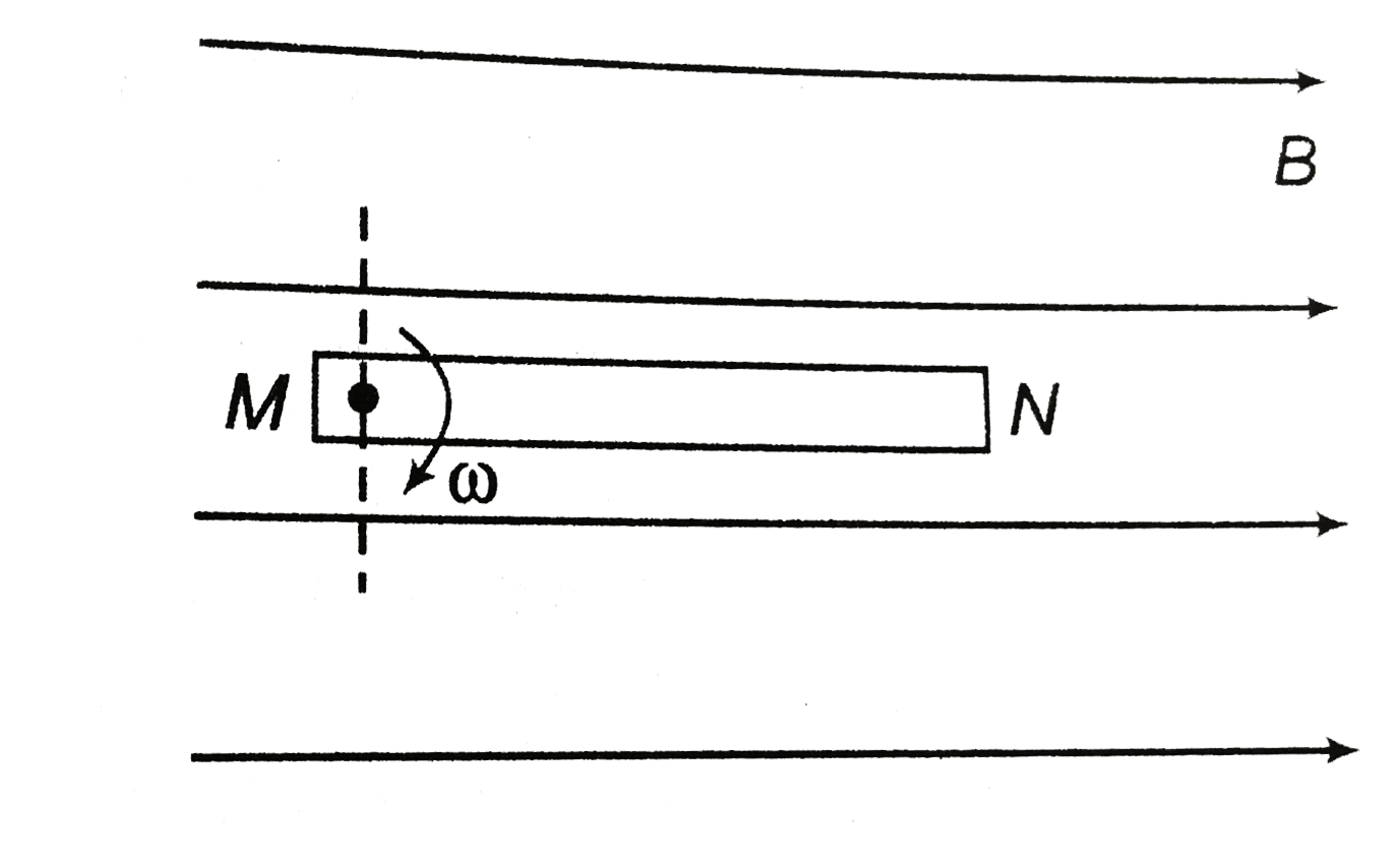
View SolutionA metallic rod of length l is hinged at the point M and is rotating about an axis perpendicular to the plane of paper with a constant angular velocity ω. A uniform magnetic field of intensity B is acting in the region (as shown in the figure) parallel to the plane of paper. The potential difference between the points M and N

View SolutionA metallic rod of length l is hinged at the point M and is rotating about an axis perpendicular to the plane of paper with a constant angular velocity ω. A uniform magnetic field of intensity B is acting in the region (as shown in the figure) parallel to the plane of paper. The potential difference between the points M and N

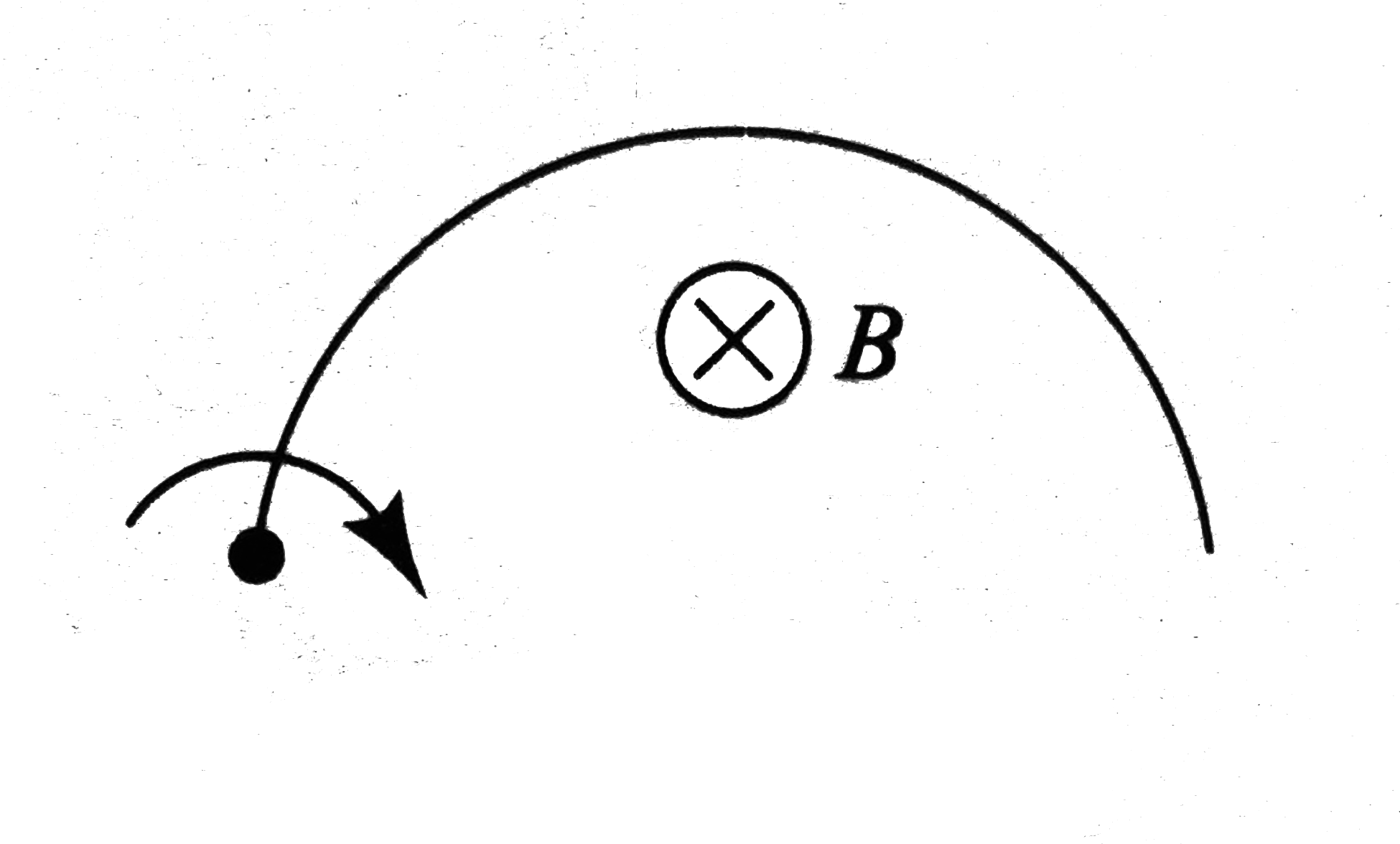
View Solutiona semicircle wire of radius R is rotated with constant angular velocity about an axis passing through one end and perpendicular to the plane of wire. There is a uniform magnetic field of strength B. The induced emf between the ends is

View Solutiona semicircle wire of radius R is rotated with constant angular velocity about an axis passing through one end and perpendicular to the plane of wire. There is a uniform magnetic field of strength B. The induced emf between the ends is

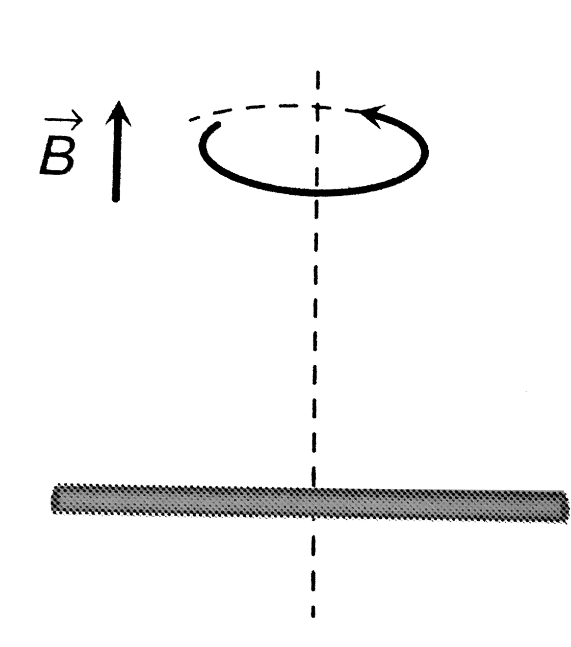
View SolutionA conducting rod of length 2l is rotating with constant angular speed w about its perpendicular bisector. A uniform magnetic field B exists parallel to the axis of rotation. The e.m.f. induced between two ends of the rod is

View SolutionA conducting rod of length 2l is rotating with constant angular speed w about its perpendicular bisector. A uniform magnetic field B exists parallel to the axis of rotation. The e.m.f. induced between two ends of the rod is

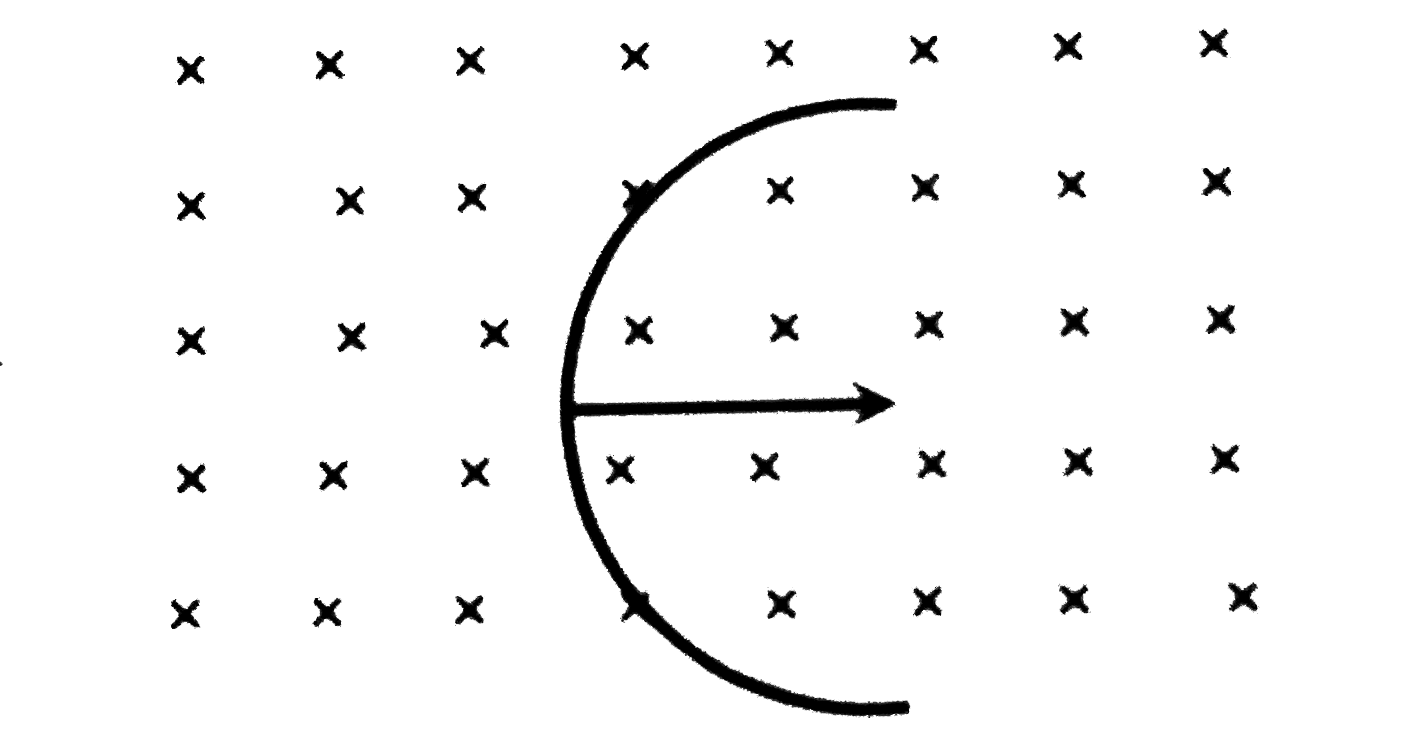
View SolutionA straight wire of length L is bent into a semicircle. It is moved in a uniform magnetic field with speed v with diameter perpendicular to the field. The induced emf between the ends of the wire is

View Solution