In a Zener regulated power supply a Zener diode with VZ=6.0 V is used for regulation. The load current is to be 4.0 mA and the unregulated input is 10.0 V. What should be the value of series resistor RS?
The correct Answer is:A
Step by step video & image solution for In a Zener regulated power supply a Zener diode with V_(Z) = 6.0 V is used for regulation. The load current is to be 4.0 mA and the unregulated input is 10.0 V. What should be the value of series resistor R_(S)? by Physics experts to help you in doubts & scoring excellent marks in Class 12 exams.
Updated on:21/07/2023Topper's Solved these Questions
- SEMICONDUCTOR ELECTRONICS (MATERIAL, DEVICES AND SIMPLE CIRUITS )BOOK - AAKASH INSTITUTE ENGLISHCHAPTER - SEMICONDUCTOR ELECTRONICS (MATERIAL, DEVICES AND SIMPLE CIRUITS )EXERCISE - EXERCISE
20 Videos
- SEMICONDUCTOR ELECTRONICS (MATERIAL, DEVICES AND SIMPLE CIRUITS )BOOK - AAKASH INSTITUTE ENGLISHCHAPTER - SEMICONDUCTOR ELECTRONICS (MATERIAL, DEVICES AND SIMPLE CIRUITS )EXERCISE - Assignment section -A (Objective Type Question)
43 Videos
- SEMICONDUCTOR ELECTRONICS (MATERIAL, DEVICES AND SIMPLE CIRUITS )BOOK - AAKASH INSTITUTE ENGLISHCHAPTER - SEMICONDUCTOR ELECTRONICS (MATERIAL, DEVICES AND SIMPLE CIRUITS )EXERCISE - Assignment SECTION - D (Assertion & reason type Question)
10 Videos
- RAY OPTICS AND OPTICAL INSTRUMENTSBOOK - AAKASH INSTITUTE ENGLISHCHAPTER - RAY OPTICS AND OPTICAL INSTRUMENTSEXERCISE - ASSIGNMENT (SECTION - D)
16 Videos
- SEMICONDUCTOR ELECTRONICS: MATERIALS, DEVICES AND SIMPLE CIRCUITSBOOK - AAKASH INSTITUTE ENGLISHCHAPTER - SEMICONDUCTOR ELECTRONICS: MATERIALS, DEVICES AND SIMPLE CIRCUITSEXERCISE - Assignment (Section-D (Assertion and reason))
5 Videos
Similar Questions
In a zener regulated power supply a zener diode with
Vz=6.0V is used for regualtion. The load current is to eb 4.0 mA and the
unregulated input is 10.0 V . What should be the value of series resistor R?
View Solution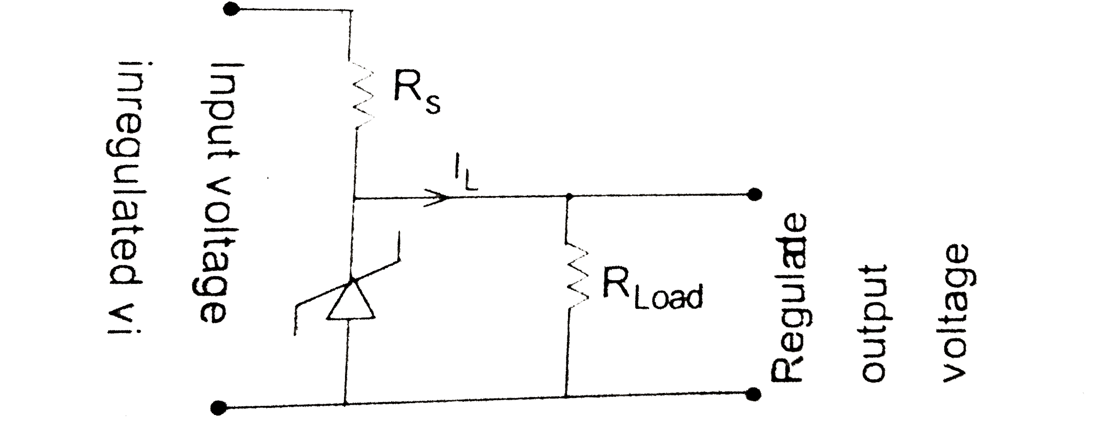
in a zener diode (dc voltage regulator) circuit with Vzener=7.0 V is used for regulation. Thhe load current is to be 4.0 mA and te unregulated input is 11.0 V. what should be te value of series resistor Rs if zener diode current is five times te load current
View Solution
Knowledge Check
A Zener of power rating 1 W is to be used as a voltage regulator. If Zener has a breakdown of 5V and it has to regulate voltage which fluctuated between 3 V and 7 V, what should be the value of Rs for safe operation (see figure) ?
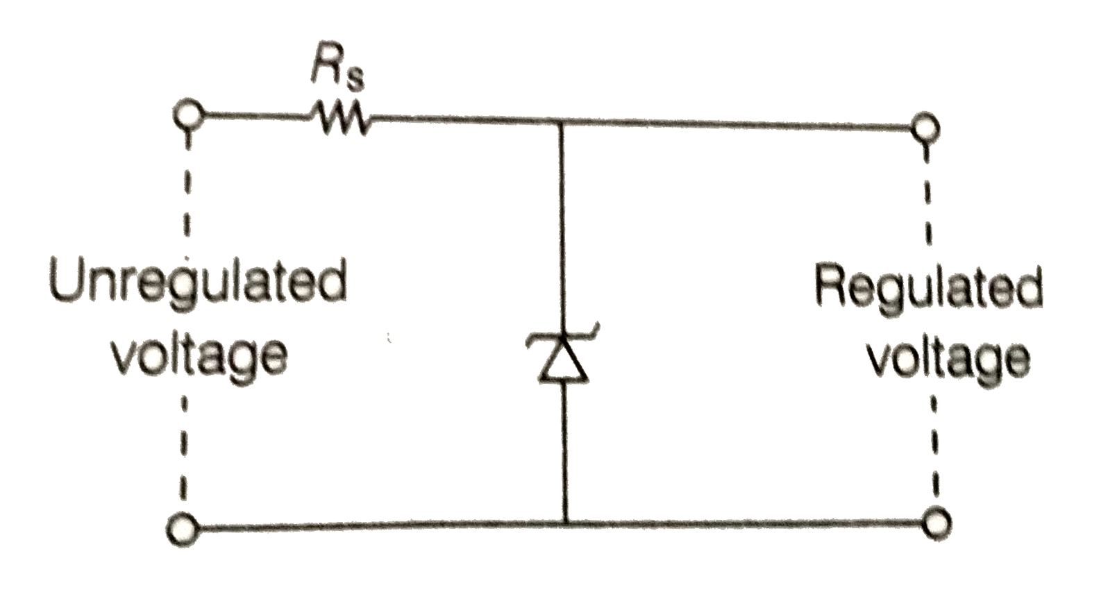 A5ΩB10ΩC15ΩD20Ω
The diode used in the circuit shown in the figure has a constant voltage drop of 0.5V at all currents and a maximum power rating fo 100 milliwatts. What should be the value of the resistor R, connected in series with the diode for obtaining maximum current?
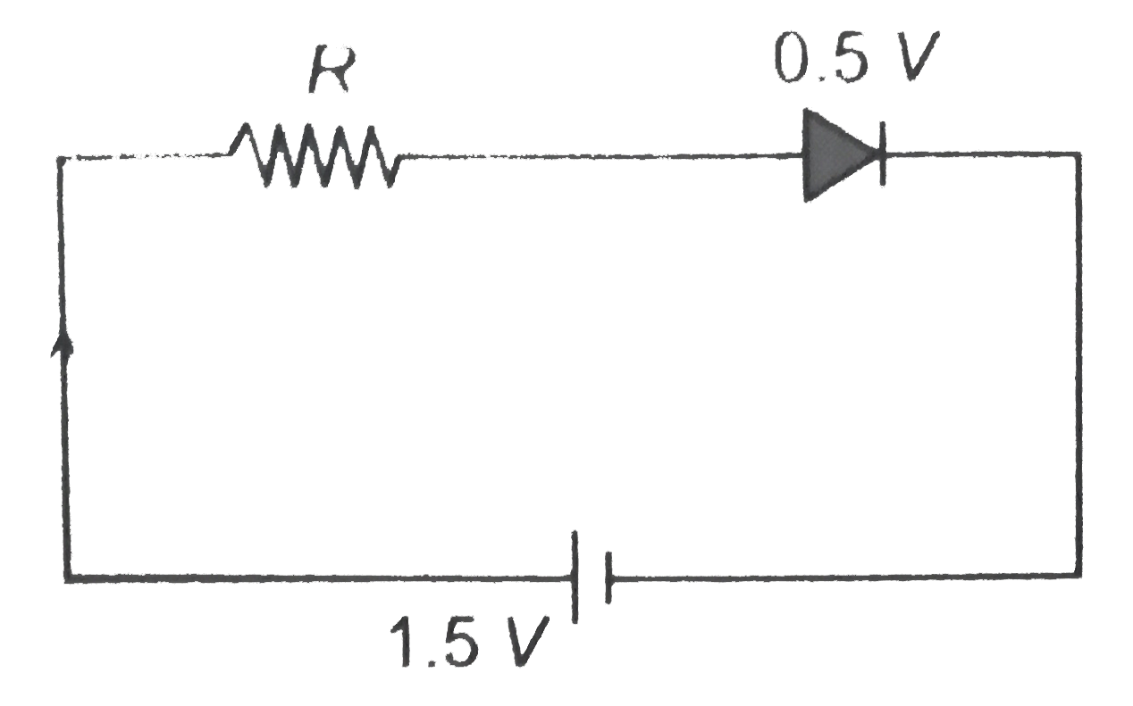 A6.76ΩB20ΩC5ΩD5.6Ω
In the cuircuit shown here the transistor used has a current gain β=100. What should be the bias resistor RBE so that VCE=5V(neglect VBE)
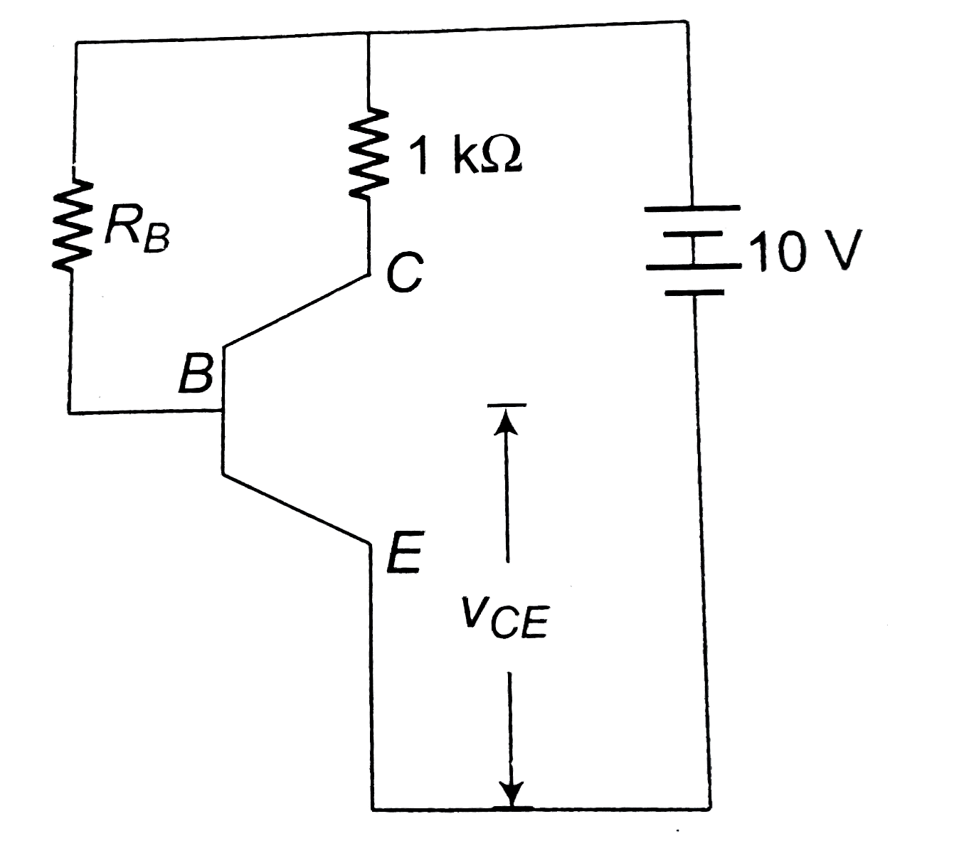 A200×103ΩB1×106ΩC500ΩD2×103Ω
(A) Plot V-I characteristics for an illuminated photo diode under reverse bias for three different illumination intensities I1>I2>I3 . (B) In a zener regulated power supply, a zener diode with V_2 = 6 V is used for regulation. the load current should be 4.0 mA and zener current is five times the load current for unregulated input of 10 V. Find the series resistor R3 used in the power supply.
View SolutionA Zener of power rating 1 W is to be used as a voltage regulator. If Zener has a breakdown of 5V and it has to regulate voltage which fluctuated between 3 V and 7 V, what should be the value of Rs for safe operation (see figure) ?

View SolutionThe diode D shown in the circuit is governed by the V-I relation V=(0.7+100I) Volt. The current supplied by the battery is
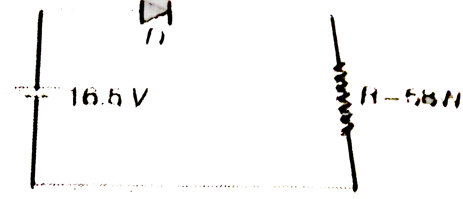
View SolutionA resistor and a capacitor are connected to an ac supply of 200 V, 50 Hz, in series. The current in the circuit is 2A. If the power consumed in the circuit is 100 W then the resistance in the circuit is
View SolutionA resistor and a capacitor are connected to an ac supply of 200 V, 50 Hz, in series. The current in the circuit is 2A. If the power consumed in the circuit is 100 W then the resistance in the circuit is
View Solution
