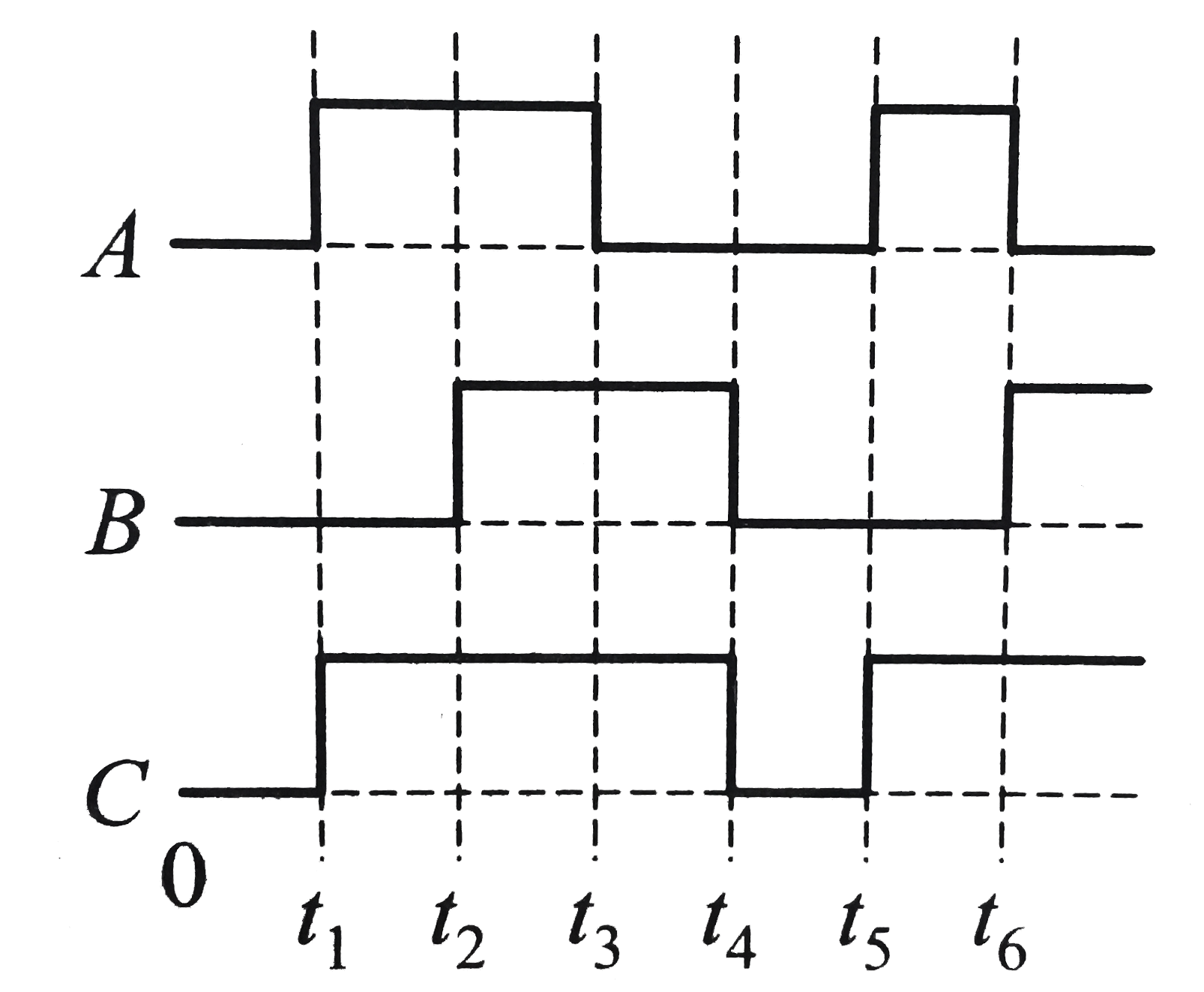
The following figure shows a logic gate circuit with two inputs A and B and the output C. The voltage waveforms of A, B and C are as given The logic circuit is:
AND gate
NAND gate
NOR gate
OR gate
The correct Answer is:A
To determine the logic gate circuit based on the given voltage waveforms of inputs A, B, and output C, we can follow these steps:
1. Analyze the Input Waveforms:
- Observe the voltage levels of inputs A and B over time. Identify when each input is high (1) and low (0).
2. Observe the Output Waveform:
- Look at the output waveform C and note when it is high (1) and low (0).
3. Determine the Relationship:
- Compare the states of inputs A and B with the output C. Check for the conditions under which C is high.
4. Identify Logic Gate Behavior:
- If C is high only when both A and B are high, then the logic gate is an AND gate. This is because an AND gate outputs high only when both inputs are high.
5. Conclusion:
- Based on the analysis, conclude that the logic circuit is an AND gate.
Final Answer:
The logic circuit is an AND gate.
- Observe the voltage levels of inputs A and B over time. Identify when each input is high (1) and low (0).
- Look at the output waveform C and note when it is high (1) and low (0).
- Compare the states of inputs A and B with the output C. Check for the conditions under which C is high.
- If C is high only when both A and B are high, then the logic gate is an AND gate. This is because an AND gate outputs high only when both inputs are high.
- Based on the analysis, conclude that the logic circuit is an AND gate.
The logic circuit is an AND gate.
Topper's Solved these Questions
- SEMICONDUCTOR ELECTRONICS (MATERIAL, DEVICES AND SIMPLE CIRUITS )BOOK - AAKASH INSTITUTE ENGLISHCHAPTER - SEMICONDUCTOR ELECTRONICS (MATERIAL, DEVICES AND SIMPLE CIRUITS )EXERCISE - Assignment SECTION - D (Assertion & reason type Question)
10 Videos
- SEMICONDUCTOR ELECTRONICS (MATERIAL, DEVICES AND SIMPLE CIRUITS )BOOK - AAKASH INSTITUTE ENGLISHCHAPTER - SEMICONDUCTOR ELECTRONICS (MATERIAL, DEVICES AND SIMPLE CIRUITS )EXERCISE - Assignment section -B (Objective Type Question)
29 Videos
- RAY OPTICS AND OPTICAL INSTRUMENTSBOOK - AAKASH INSTITUTE ENGLISHCHAPTER - RAY OPTICS AND OPTICAL INSTRUMENTSEXERCISE - ASSIGNMENT (SECTION - D)
16 Videos
- SEMICONDUCTOR ELECTRONICS: MATERIALS, DEVICES AND SIMPLE CIRCUITSBOOK - AAKASH INSTITUTE ENGLISHCHAPTER - SEMICONDUCTOR ELECTRONICS: MATERIALS, DEVICES AND SIMPLE CIRCUITSEXERCISE - Assignment (Section-D (Assertion and reason))
5 Videos
Similar Questions
The figure shows a logic circuit with two inputs A and B and the output C. The voltage wave forms across A,B and C are as given. The logic circuit gate is
View SolutionThe following figure shows a logic gate circuit with two inputs A and B output C. The voltage waveforms of A,B and C are as shown in second figure given below :-
_E01_436_Q01.png)
The logic circuit gate is :-
View Solution
Knowledge Check
The following figure shows a logic gate circuit with two inputs A and B and the output Y. The voltage waveforms of A,B and Y are as given :
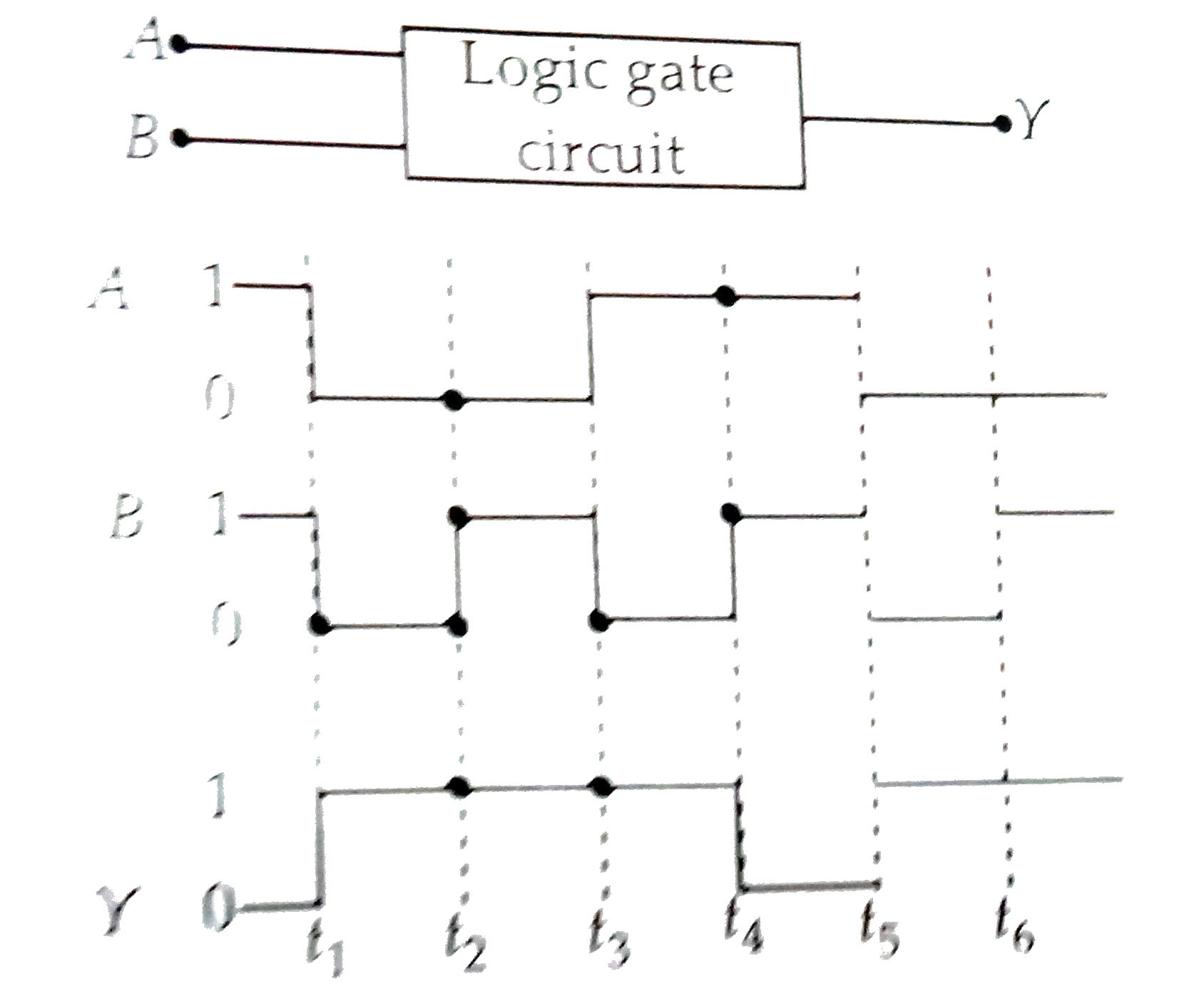
The logic gate isANOR gateBOR gateCAND gateDNAND gate
the output given logic circuit is :
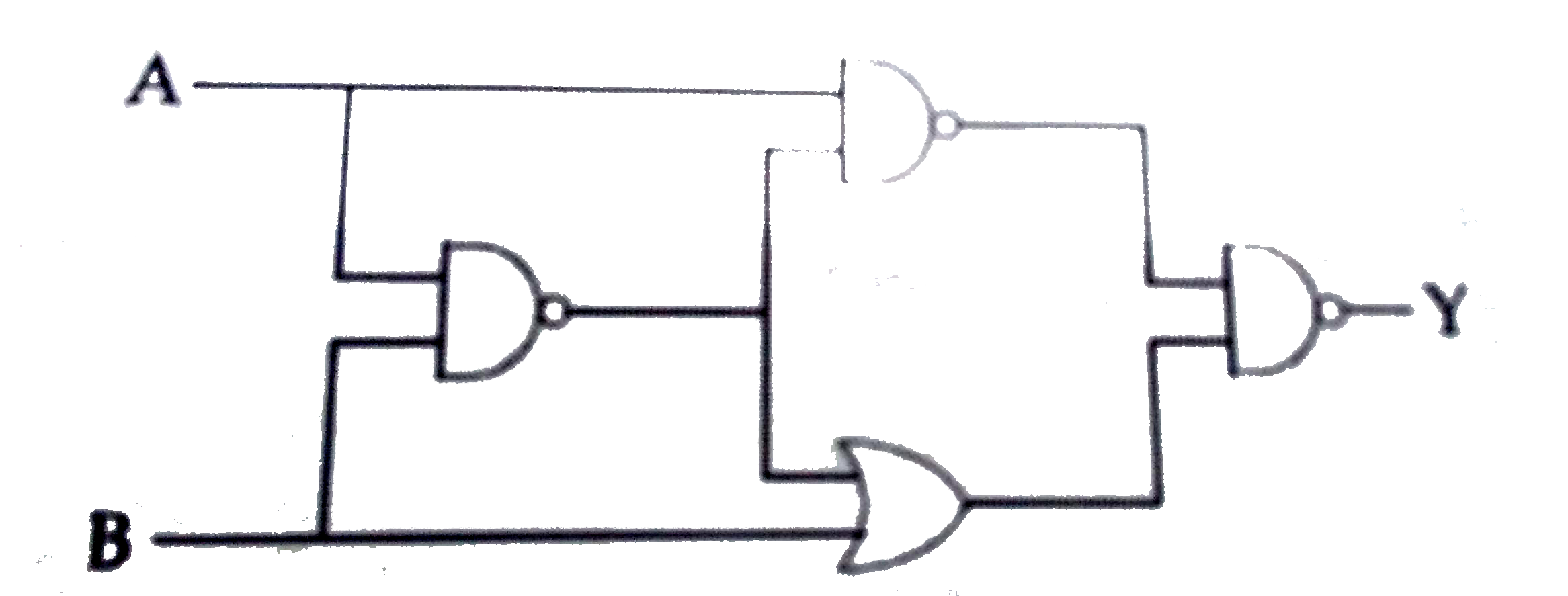
View SolutionThe output of the given logic circuit is
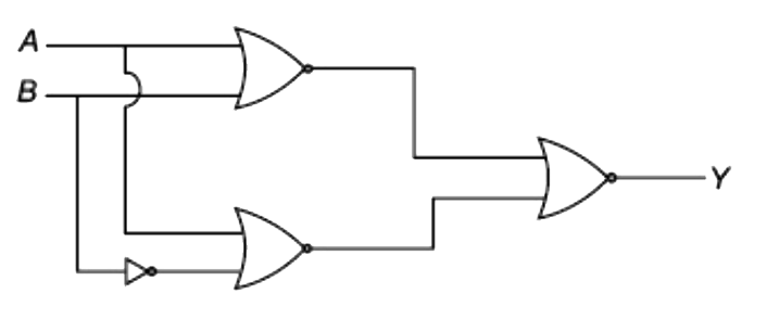
View SolutionThere is a gate with two inputs A and B, and one output Y. using the input and output wave forms identify the gate
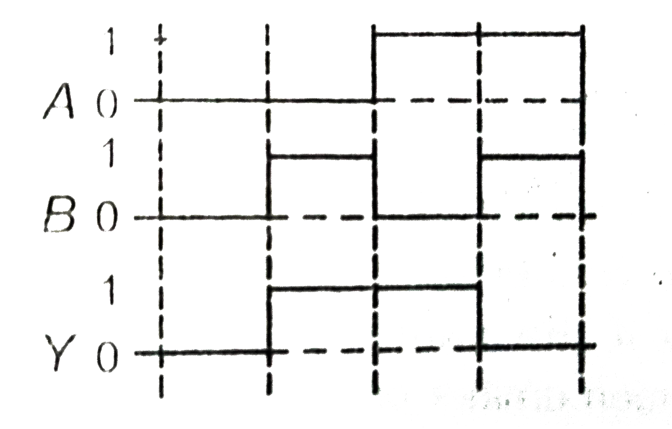
View Solution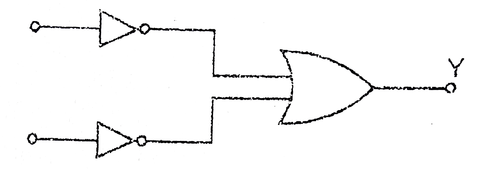
The output Y for the following logic gate circuit will be-
View SolutionThe symbolic form of logic of the circuit given below is
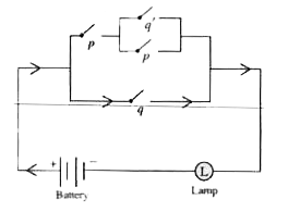
View SolutionThe output of the given logic gate is 1 when inputs A,B and C are such that :-
_E01_413_Q01.png)
View SolutionThe logic gate equivalent to the given logic circuit is :
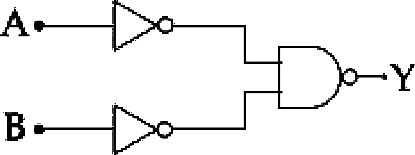
View Solution
