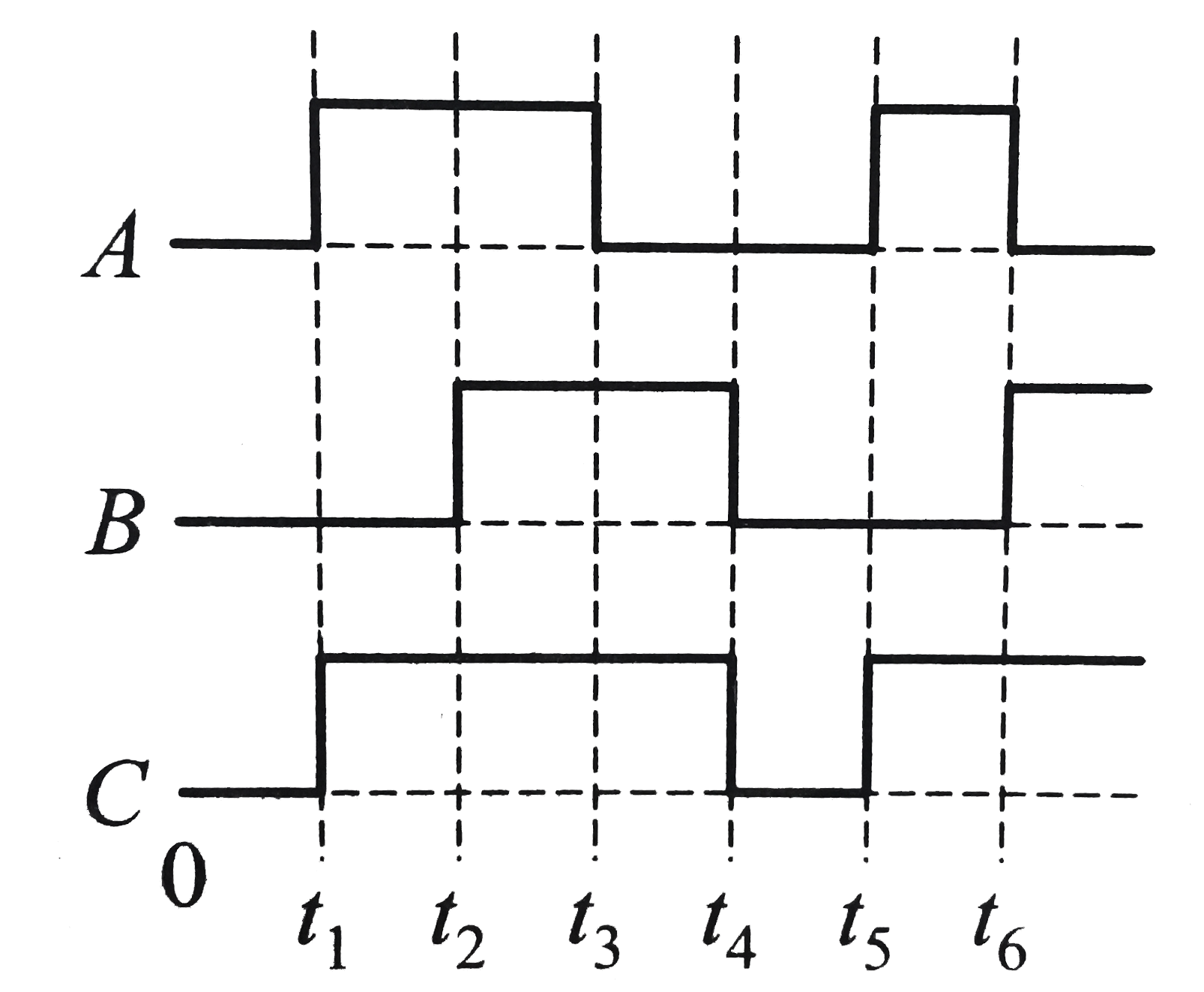
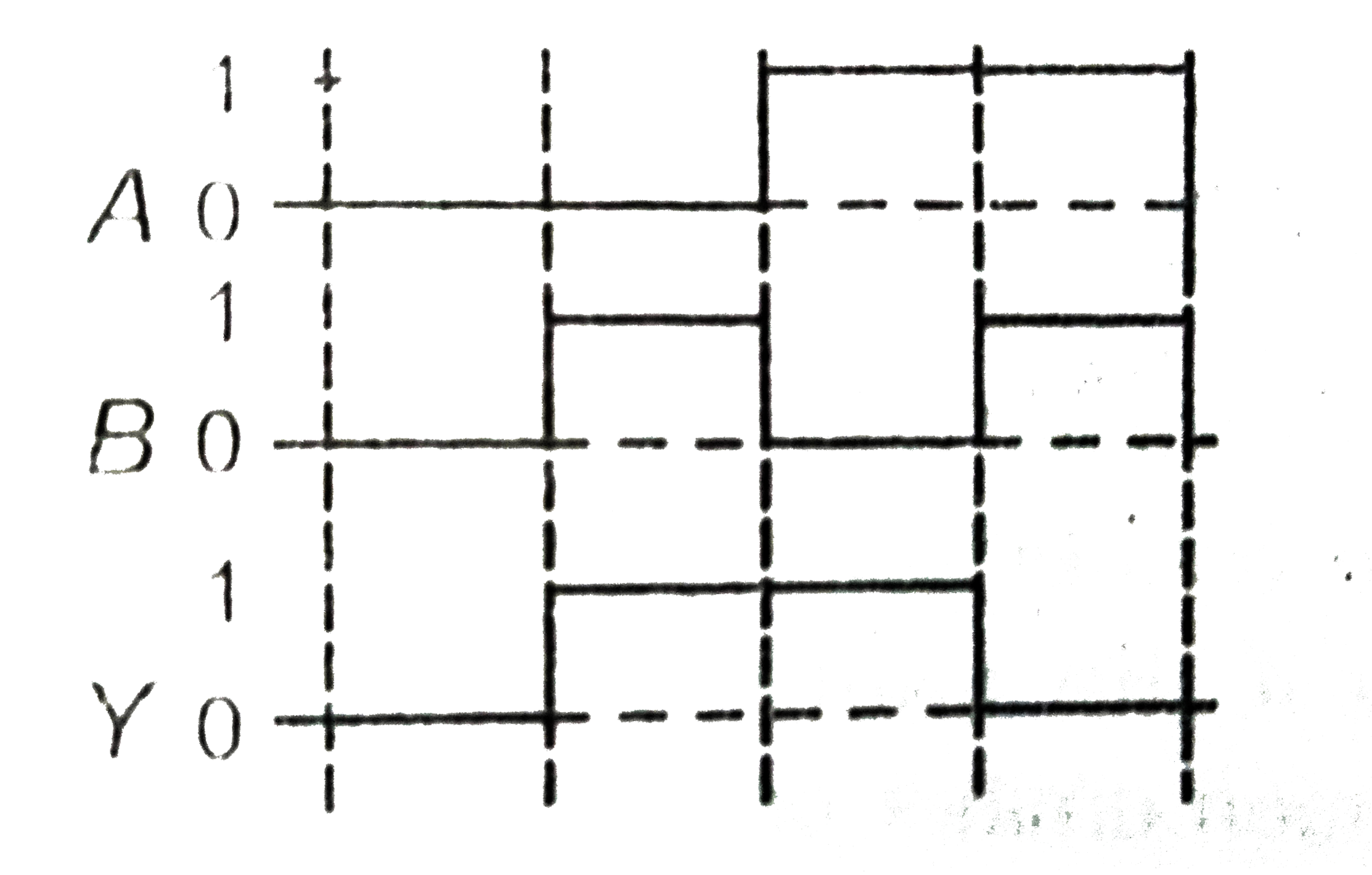
The figure shows a logic circuit with two inputs A and B and the output C. The voltage wave forms across A,B and C are as given. The logic circuit gate is
OR gate
NOR gate
AND gate
NAND gate
The correct Answer is:A
Step by step video & image solution for The figure shows a logic circuit with two inputs A and B and the output C. The voltage wave forms across A,B and C are as given. The logic circuit gate is by Physics experts to help you in doubts & scoring excellent marks in Class 12 exams.
Updated on:21/07/2023Similar Questions
The following figure shows a logic gate circuit with two inputs A and B and the output C. The voltage waveforms of A, B and C are as given The logic circuit is:
View SolutionThe following figure shows a logic gate circuit with two inputs A and B output C. The voltage waveforms of A,B and C are as shown in second figure given below :-
_E01_436_Q01.png)
The logic circuit gate is :-
View Solution
Knowledge Check
The following figure shows a logic gate circuit with two inputs A and B and the output Y. The voltage waveforms of A,B and Y are as given :
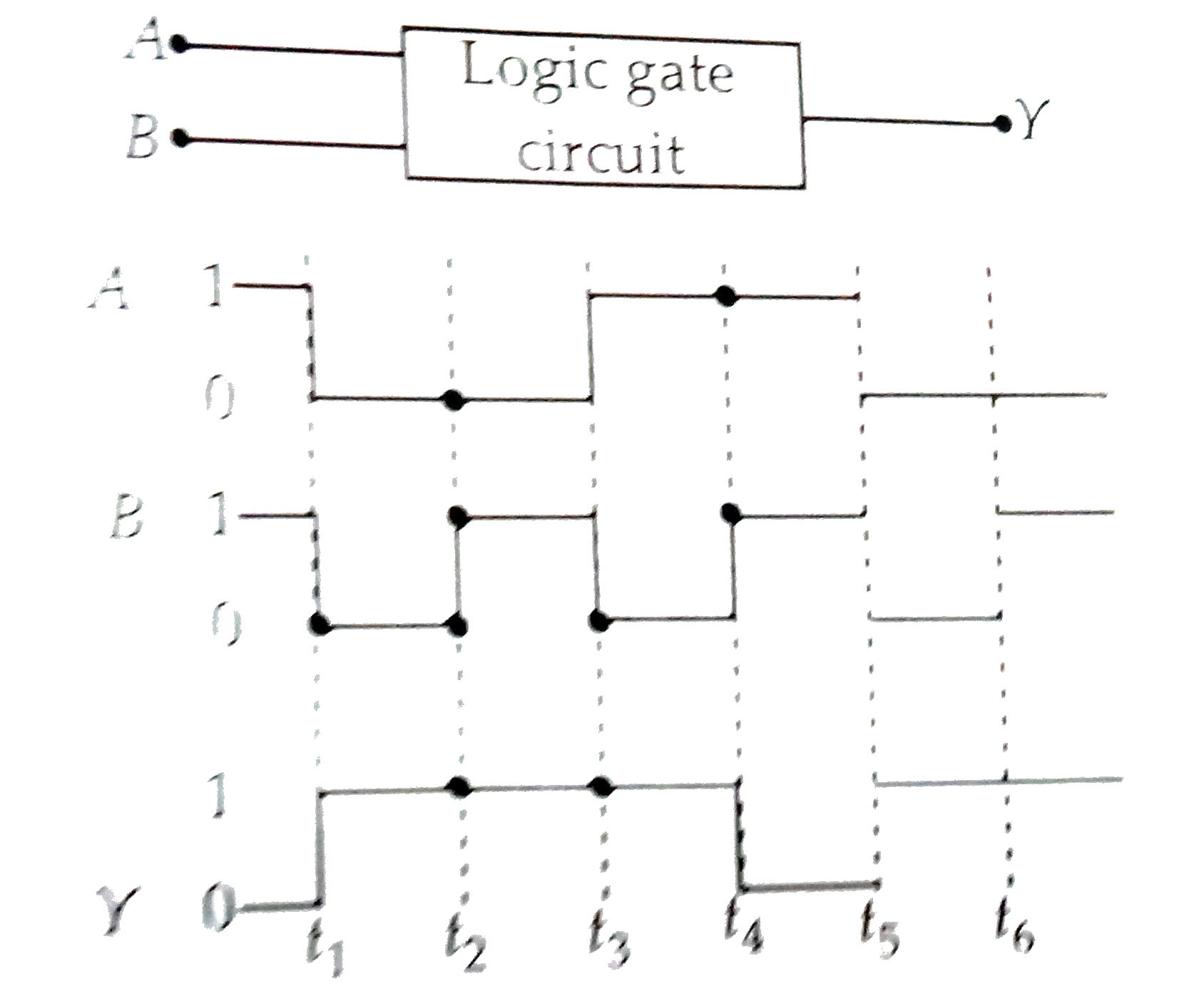
The logic gate isANOR gateBOR gateCAND gateDNAND gate
the output given logic circuit is :
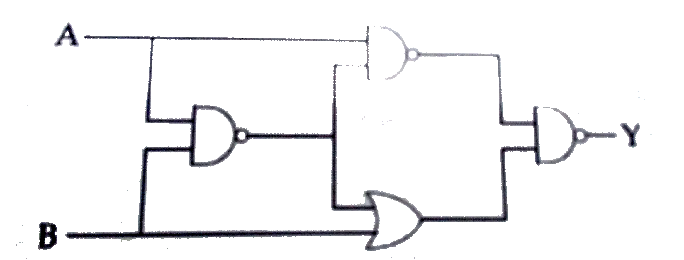
View SolutionThe output of the given logic circuit is
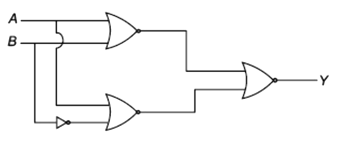
View SolutionThere is a gate with two inputs A and B, and one output Y. using the input and output wave forms identify the gate
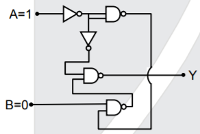
View SolutionThe output of the given logic gate is

View SolutionThe output of the following logic circuit is

View SolutionOutput at terminal Y of given logic circuit.
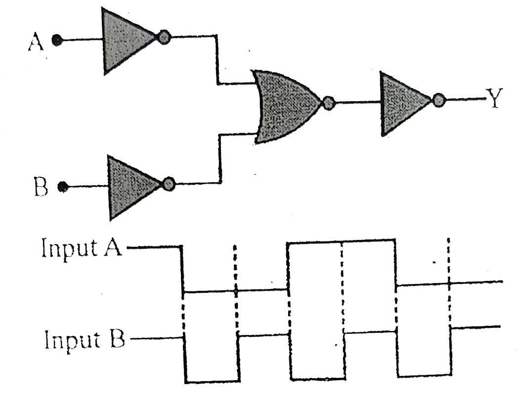
View SolutionThe logic circuit shown has the input waveforms 'A' and 'B' as shown. Pick out the CORRECT output waveform:-
View Solution
