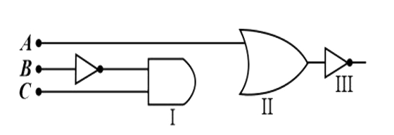
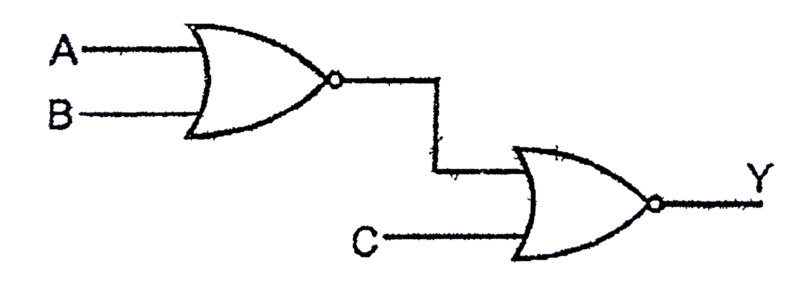
The output Y for logic diagram shown below is
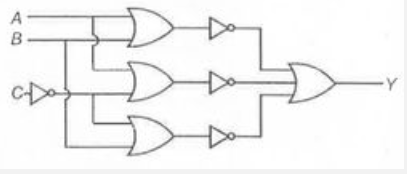
Y=¯¯¯A+¯¯¯B+¯¯¯C
Y=¯¯¯¯¯¯¯¯A.B+¯¯¯A.C+¯¯¯B.C
Y=(¯¯¯¯¯¯¯¯¯¯¯A+B)+(¯¯¯¯¯¯¯¯¯¯¯B+C)+(¯¯¯¯¯¯¯¯¯¯¯C+A)
Y=¯¯¯AB+¯¯¯B.C+¯¯¯CA
The correct Answer is:B
Step by step video & image solution for The output Y for logic diagram shown below is by Physics experts to help you in doubts & scoring excellent marks in Class 12 exams.
Updated on:21/07/2023Topper's Solved these Questions
Similar Questions
Knowledge Check
In the diagram shown below:
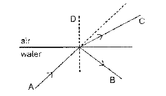 AB is incident ray and C is refracted ray.BA is incident ray and B is refracted ray.CC is incident ray and Bis refracted ray.DA is incident ray and C is refracted ray.
The logic circuit shown below has the input waveforems 'A' and 'B' as shown. Pick out the correct output waveform
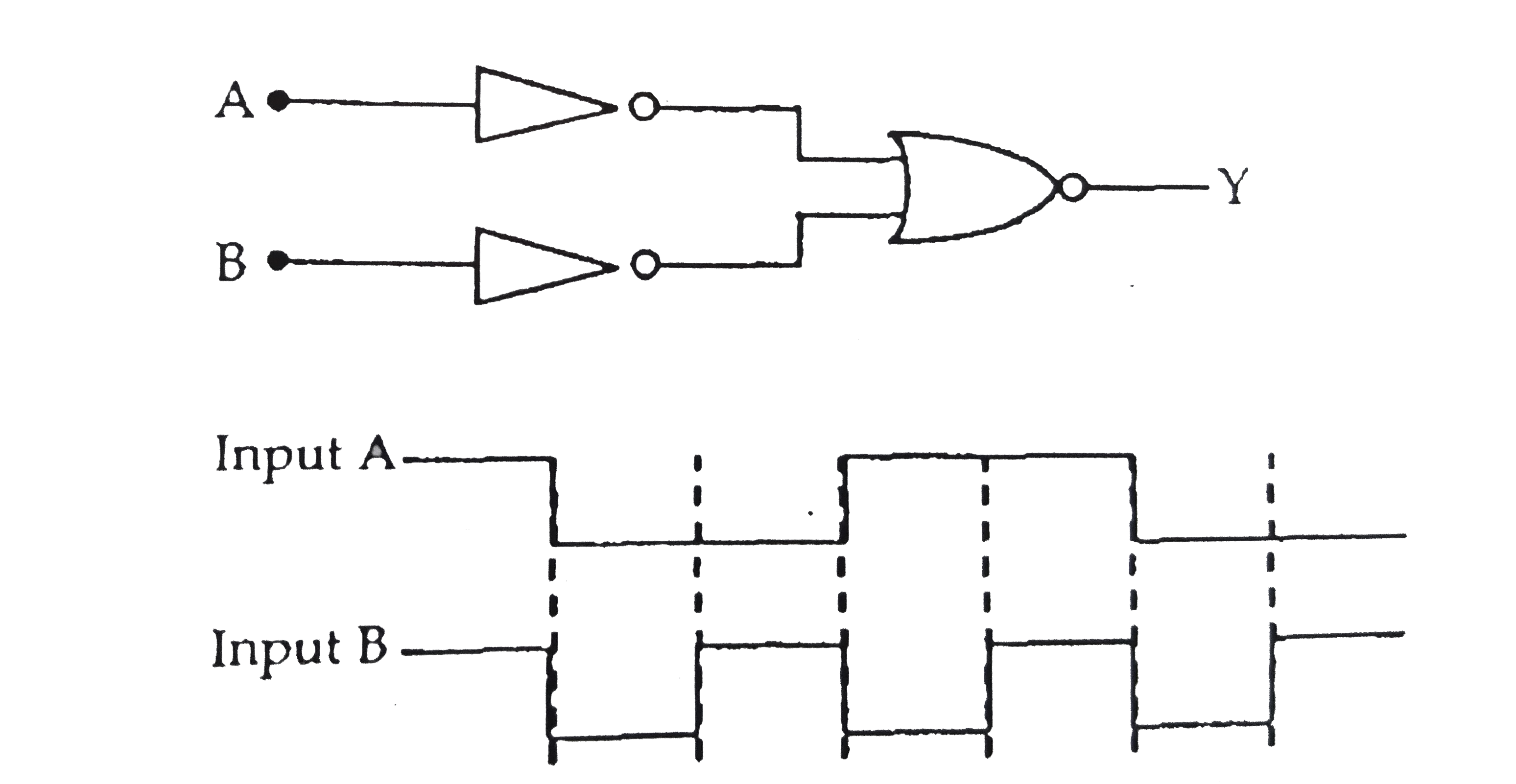 A
A B
B C
C D
D
The Boolean expression for the output Y of the logic operation shown is-
View SolutionThe output (X) of the logic circuit shown in figure will be

View SolutionWrite the truth table for the logic circuit shown below and identify the logic operation performed by circuit.
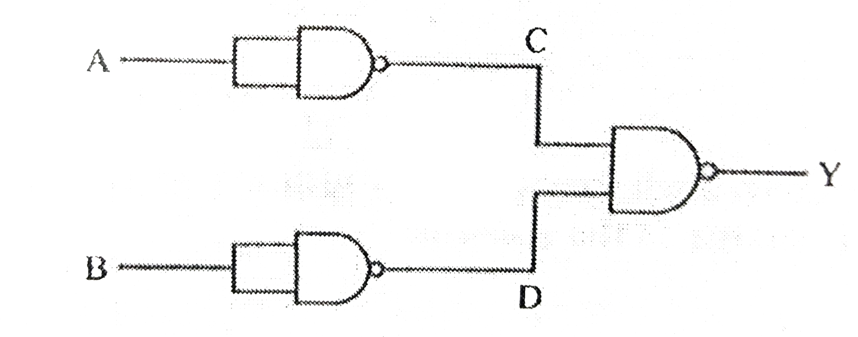
View SolutionWrite the truth table for the logic circuit shown below and identify the logic operation performed by circuit.

View SolutionComplete the ray diagram shown below, given that the critical angle. for air-glass pair is ic=42∘
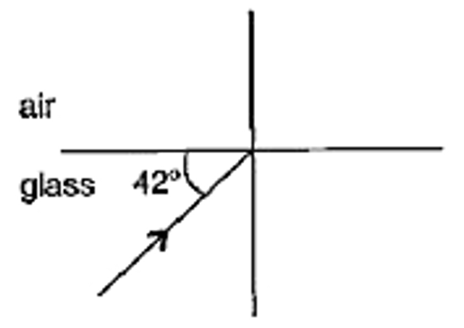
View SolutionThe output of the given logic gate is

View Solution
