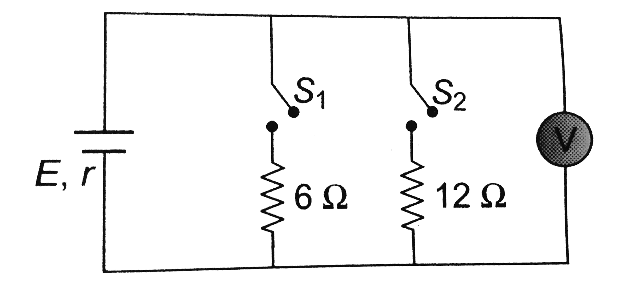
In the circuit shown in figure reading of voltmeter is V1 when only S1 is closed, reading of voltmeter is V2 when only S2 is closed and reading of voltmeter is V3 when both S1 and S2 are closed. Then
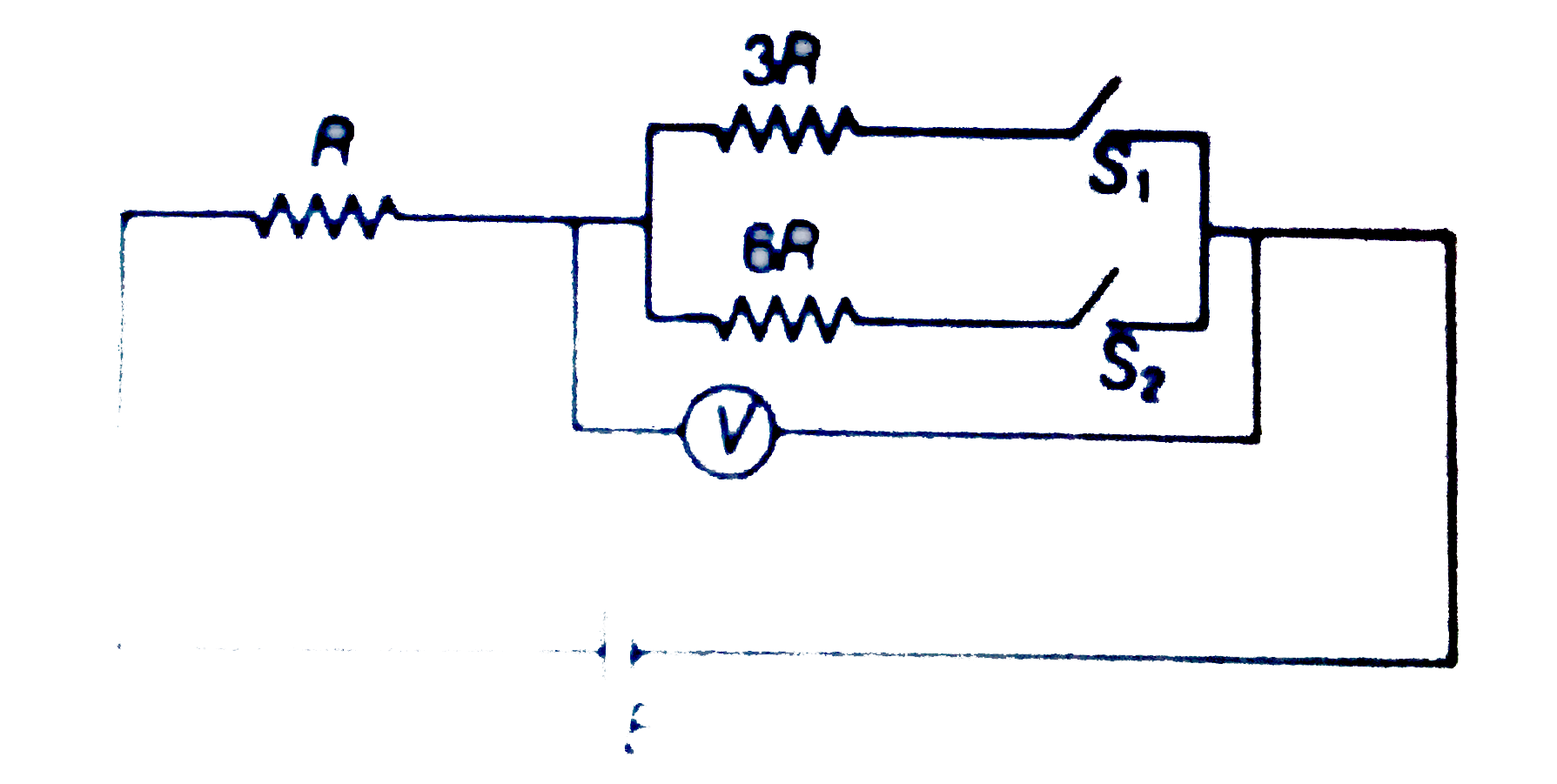
L1>L2>L3
L3>L2>L1
L3>L1>L2
L3<L2<L1
Step by step video & image solution for In the circuit shown in figure reading of voltmeter is V_(1) when only S_(1) is closed, reading of voltmeter is V_(2) when only S_(2) is closed and reading of voltmeter is V_(3) when both S_(1) and S_(2) are closed. Then by Physics experts to help you in doubts & scoring excellent marks in Class 12 exams.
Updated on:21/07/2023Similar Questions
Knowledge Check
In the circuit shown in figure, what will be the reading of the voltmeter ?
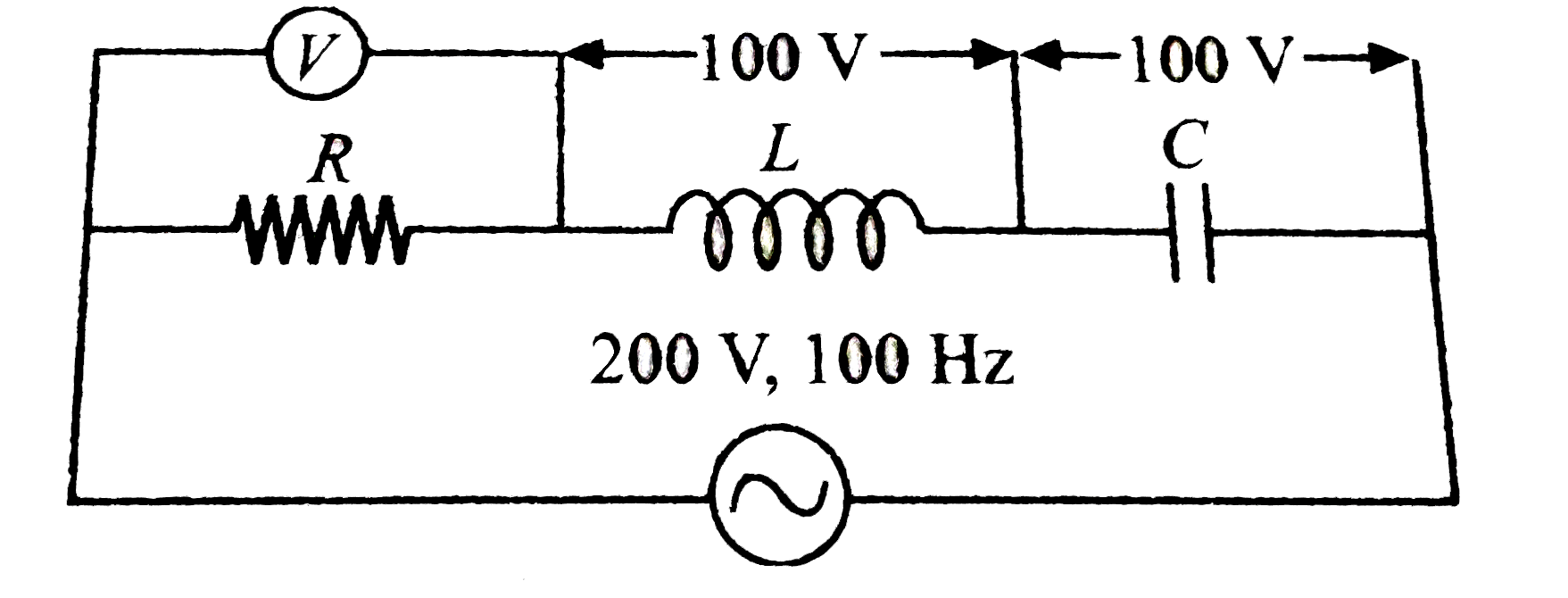 A300 VB900 VC200 VD400 V
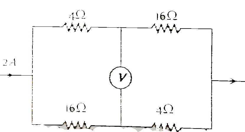
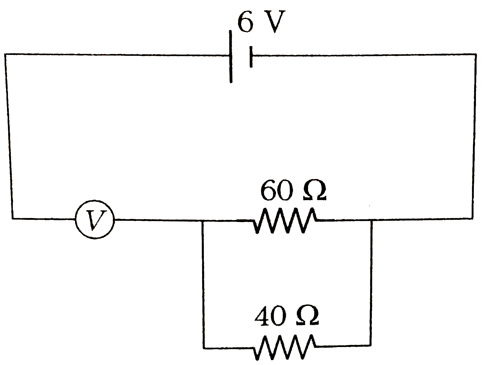
In the circuit shown in the figure, the voltmeter reading is
View SolutionIn the circuit shown, the readings of voltmeters V1,V2andV3 are given by
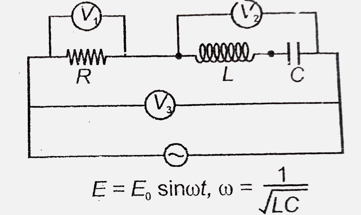
View SolutionIf the reading of volmeter V1 is 30 V, what is the reading of voltmeter V2 ?
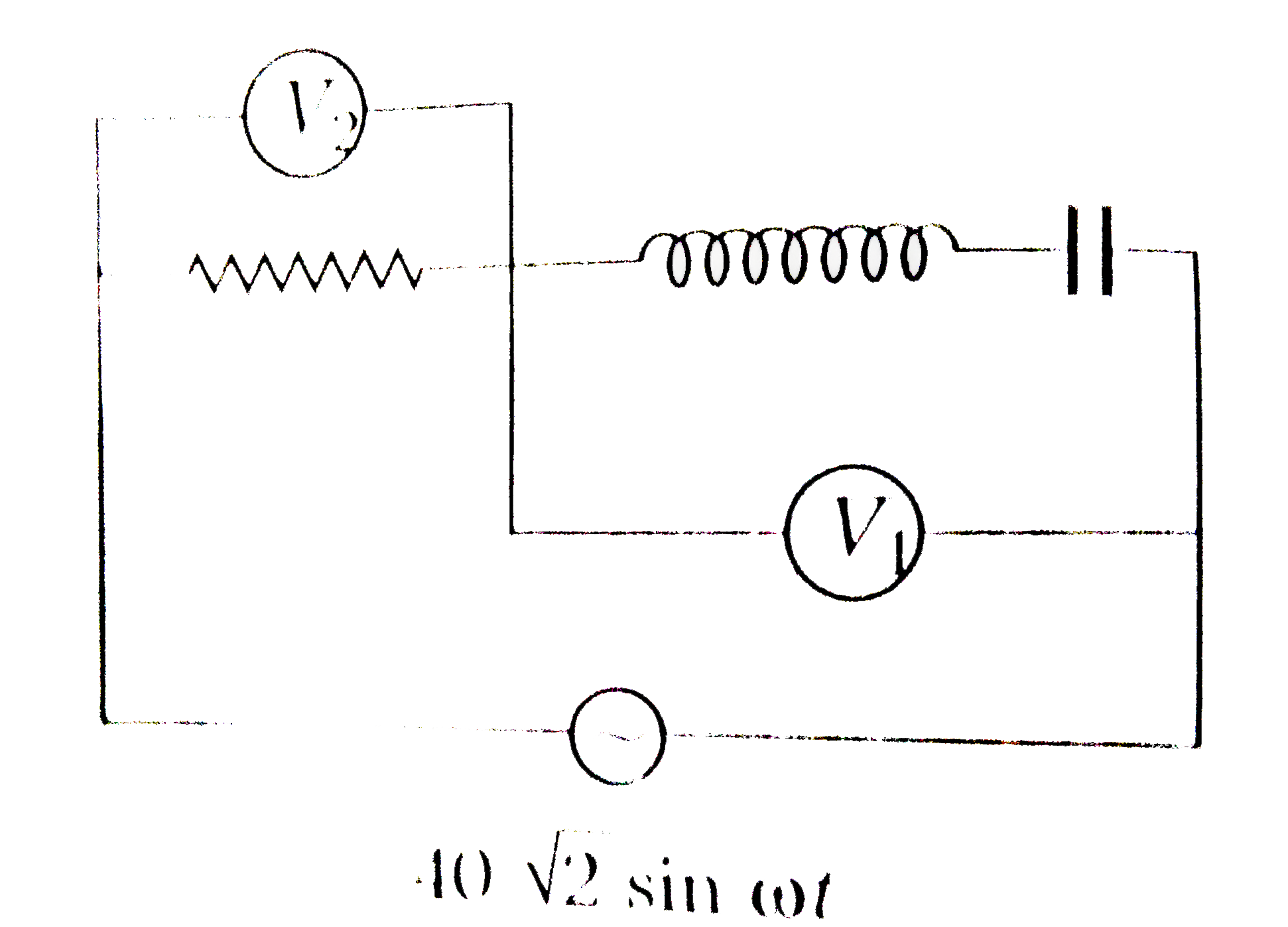
View SolutionIn the circuit shown in figure, what will be the readings of voltmeter and ammeter?
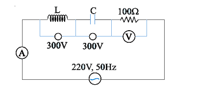
View SolutionIf the reading of coltmenter V1 is 40 V, what is the reading of voltmeter V2?

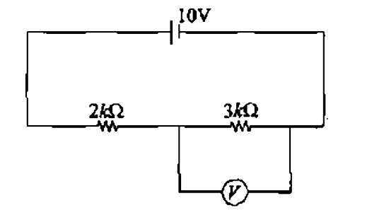
View SolutionIn the circuit shown in figure-3.334, the resistance of voltmeter is6kΩ. The voltmeter reading will be :
View SolutionIn the circuit shown, when switch S1 is closed and S2 is open, the ideal voltmeter shows a reaiding of 18V. When switch S2 is closed and S1 is open, the reading of voltmeter is 24V. When S1 and S2 both are closed, the voltmeter reading will be
View Solution

_PHY_E05_114_Q01.png) .
.