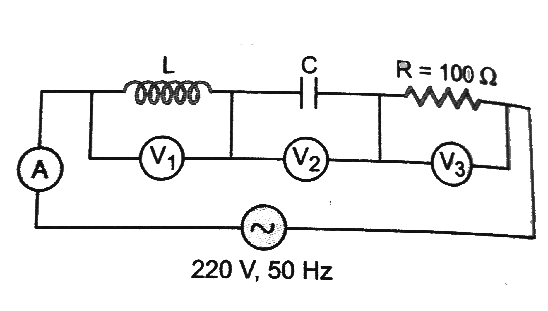
In the circuit shown, the readings of voltmeters V1,V2andV3 are given by
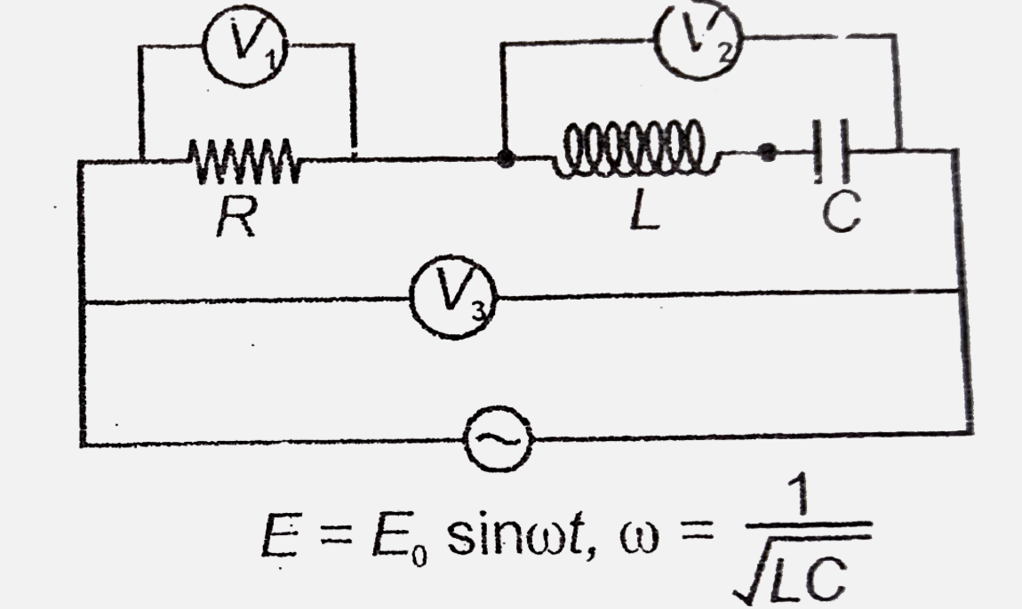
V1=V2=V3=E0
V1=V3=E0√2,V2=0
V1=V3=E0,V2=0
V1=E0√2,V2=V3=0
The correct Answer is:B
Step by step video & image solution for In the circuit shown, the readings of voltmeters V_(1), V_(2) and V_(3) are given by by Physics experts to help you in doubts & scoring excellent marks in Class 12 exams.
Updated on:21/07/2023Topper's Solved these Questions
- ALTERNATING CURRENT BOOK - AAKASH INSTITUTE ENGLISHCHAPTER - ALTERNATING CURRENT EXERCISE - Assignment (Section - C ) (Objective Type Questions) ( More than one option are correct)
2 Videos
- ALTERNATING CURRENT BOOK - AAKASH INSTITUTE ENGLISHCHAPTER - ALTERNATING CURRENT EXERCISE - Assignment (Section - D) (Linked Comprehension Type Questions)
3 Videos
- ALTERNATING CURRENT BOOK - AAKASH INSTITUTE ENGLISHCHAPTER - ALTERNATING CURRENT EXERCISE - Assignment (Section - A) ( Objective Type Questions ( One option is correct))
40 Videos
- ATOMSBOOK - AAKASH INSTITUTE ENGLISHCHAPTER - ATOMSEXERCISE - ASSIGNMENT SECTION J (Aakash Challengers )
5 Videos
Similar Questions
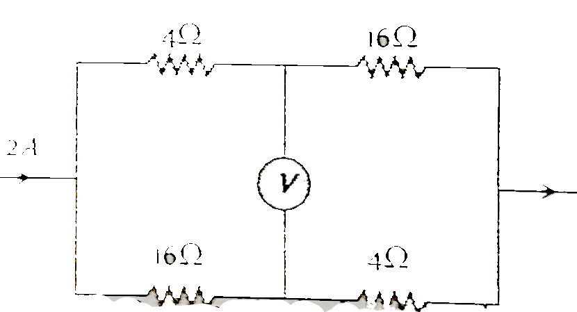
In the circuit shown below. The reading of the voltmeter V is
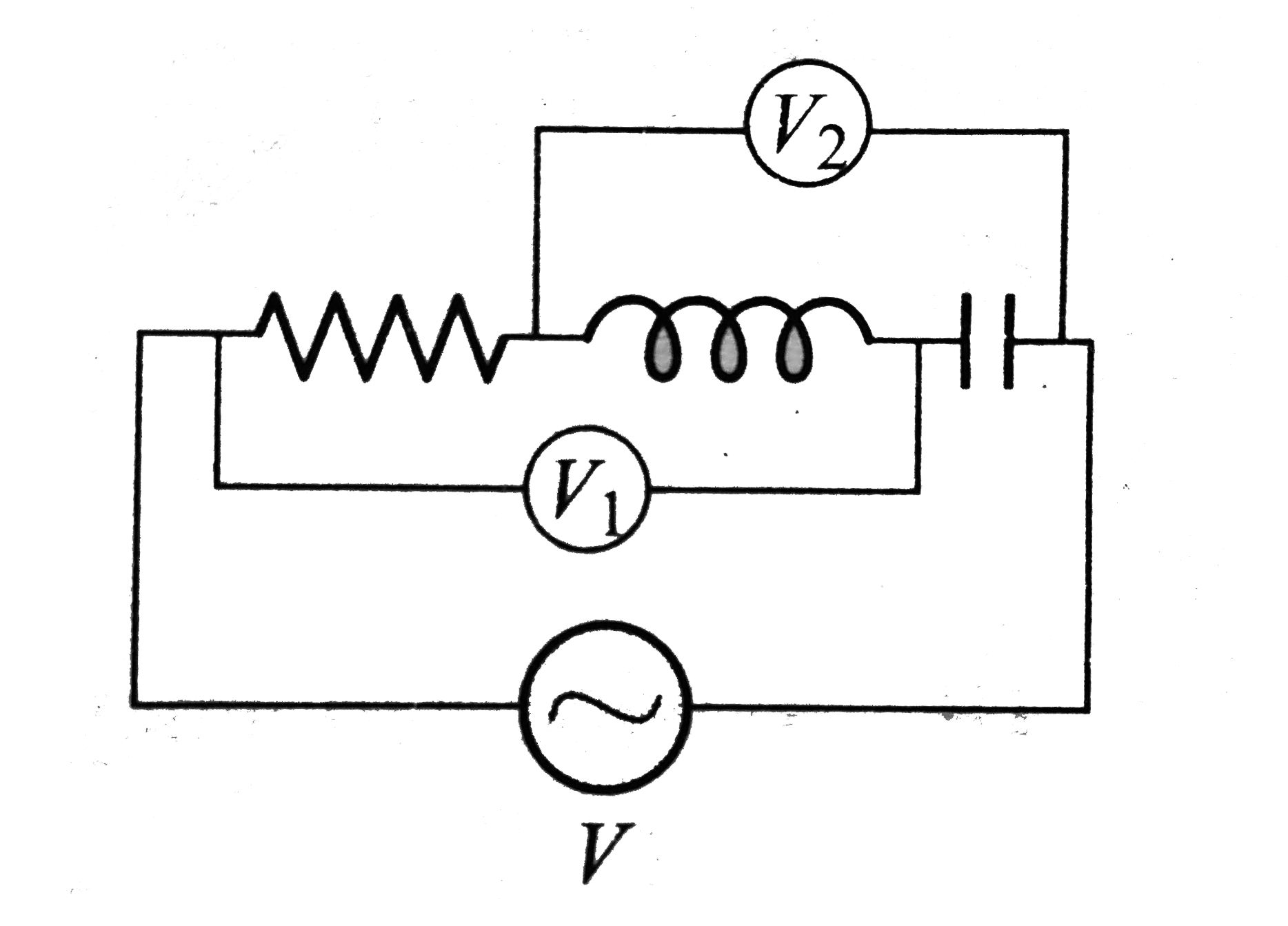
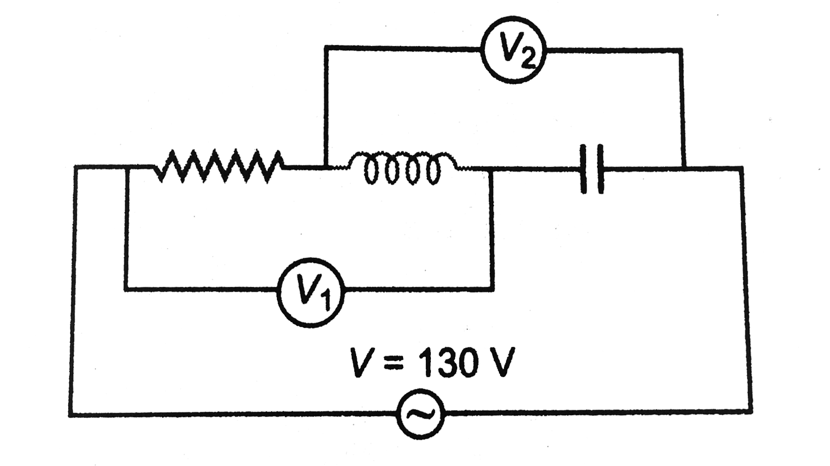
View SolutionIn an RLC series circuit shown in fig. the reading of voltmeters (V1)and(V2) are 100 V and 200 V respectively. The source voltage is 130 V. for this situation, mark out the correct statements (s).
View SolutionIn the figure shown, the reading of voltmeters are V1=40V,V2=40V and V3=10V. Find
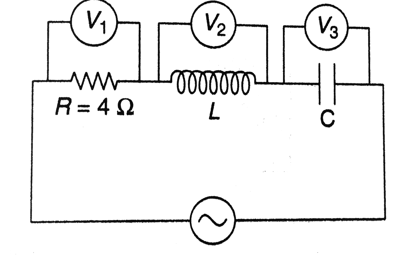
(a) the peak value of current
(b) the peak value of emf
(c) the value of L and C.
View SolutionIn the given circuit, Fig., the reading of voltmeter V1 and V2 300 votls each. The reading of the voltemeter V3 and ammeter A are respectively
View SolutionIn a R−L−C series circuit shown in readings of voltmeters V1 and V2 are 100V and 120V.
Choose the corredct statement(s).
 .
.
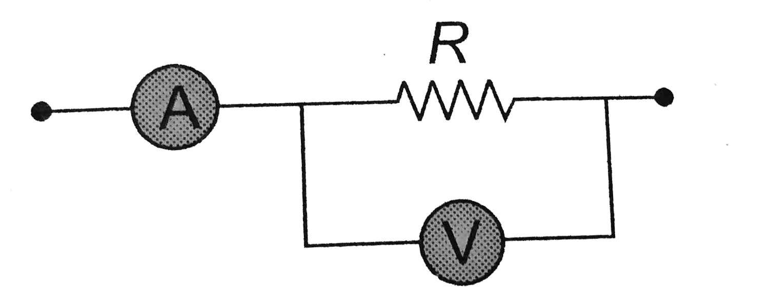
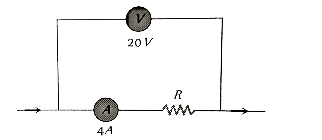
View SolutionIn the circuit shown the reading of ammeter and voltmeter are 4A and 20V respectively. The meters are non ideal, then R ia
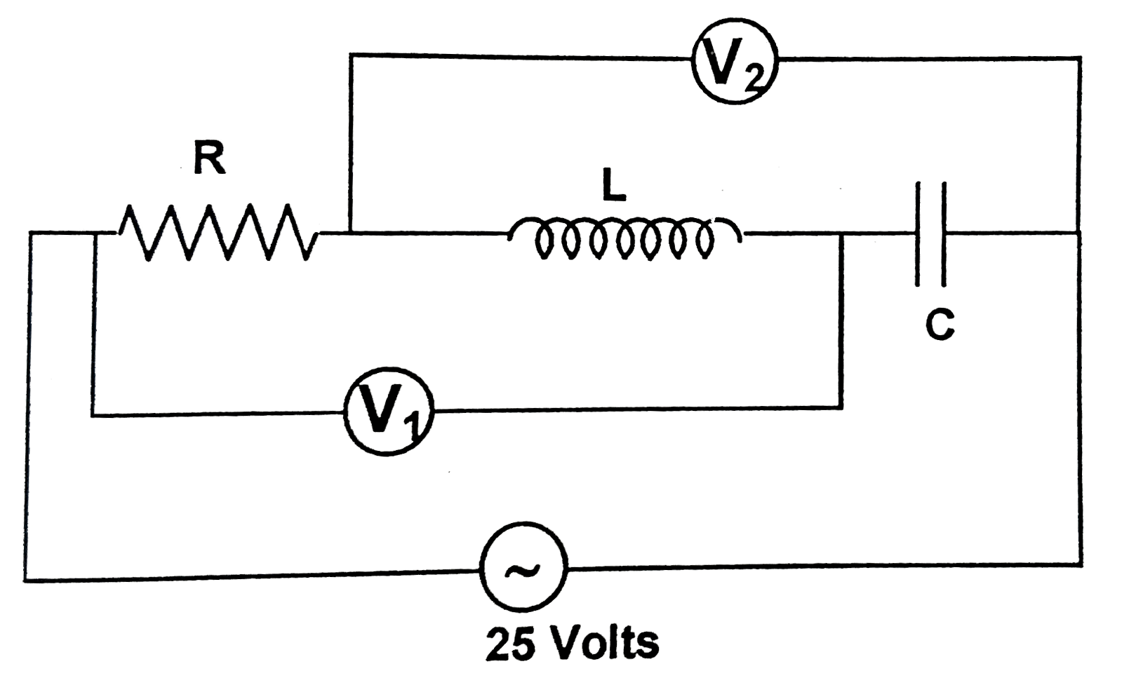
View SolutionIn an LCR series circuit, the reading of ideal voltmeters V1 and V2 are 20√2 volt and 15 volts respectively as shown in the figure (the given circuit in inductive in nature). Then
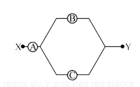
View SolutionThree voltmeters A, B and C having resistances R, 1.5 R and 3 R respectively are used in a circuit as shown. When a potential difference is applied between X and Y, the readings of the voltmeters are V1,V2andV3respectively. Then :
View SolutionIn the diagram shown, the reading of voltmeter is 20 V and that of ammeter is 4 A . The value of R should be (Consider given ammeter and voltmeter are not ideal)
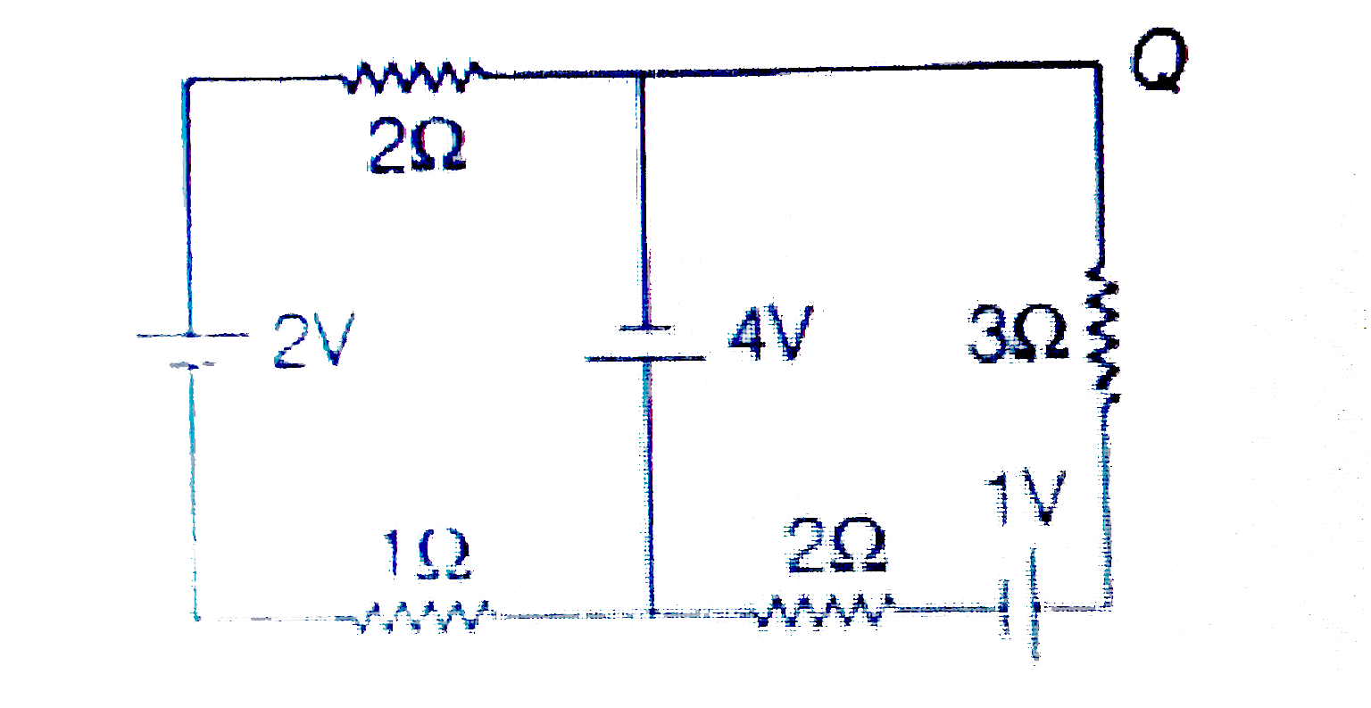
View SolutionIn the circuit shown, what is the potential different VPQ ?
View Solution
