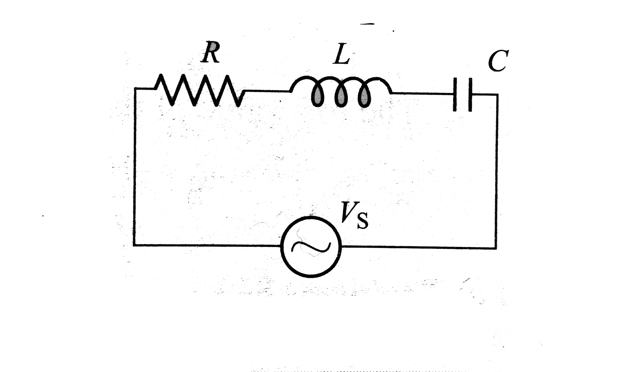
In a series LCR, AC circuit, if VL=800, VC=1600V and applied voltage is 1000V, then power factor is
0.6
0.8
1
Zero
To solve the problem, we need to find the power factor of a series LCR AC circuit given the values of the voltages across the inductor (V_L), capacitor (V_C), and the applied voltage (V_net).
1. Identify the Given Values:
- Voltage across the inductor, VL=800V
- Voltage across the capacitor, VC=1600V
- Applied voltage, Vnet=1000V
2. Determine the Voltage Difference:
- The voltage difference between the inductor and capacitor is given by:
VL−VC=800V−1600V=−800V
- This indicates that the capacitive reactance is greater than the inductive reactance.
3. Calculate the Sine of the Phase Angle (sinϕ):
- The formula for sinϕ is:
sinϕ=VL−VCVnet=−8001000=−0.8
4. Calculate the Cosine of the Phase Angle (cosϕ):
- We can find cosϕ using the Pythagorean identity:
cos2ϕ+sin2ϕ=1
- First, calculate sin2ϕ:
sin2ϕ=(−0.8)2=0.64
- Now, substitute into the identity:
cos2ϕ=1−sin2ϕ=1−0.64=0.36
- Taking the square root gives:
cosϕ=√0.36=0.6
5. Determine the Power Factor:
- The power factor is defined as cosϕ:
Power Factor=cosϕ=0.6
Final Answer:
The power factor of the circuit is 0.6.
---
- Voltage across the inductor, VL=800V
- Voltage across the capacitor, VC=1600V
- Applied voltage, Vnet=1000V
- The voltage difference between the inductor and capacitor is given by:
VL−VC=800V−1600V=−800V
- This indicates that the capacitive reactance is greater than the inductive reactance.
- The formula for sinϕ is:
sinϕ=VL−VCVnet=−8001000=−0.8
- We can find cosϕ using the Pythagorean identity:
cos2ϕ+sin2ϕ=1
- First, calculate sin2ϕ:
sin2ϕ=(−0.8)2=0.64
- Now, substitute into the identity:
cos2ϕ=1−sin2ϕ=1−0.64=0.36
- Taking the square root gives:
cosϕ=√0.36=0.6
- The power factor is defined as cosϕ:
Power Factor=cosϕ=0.6
The power factor of the circuit is 0.6.
Similar Questions
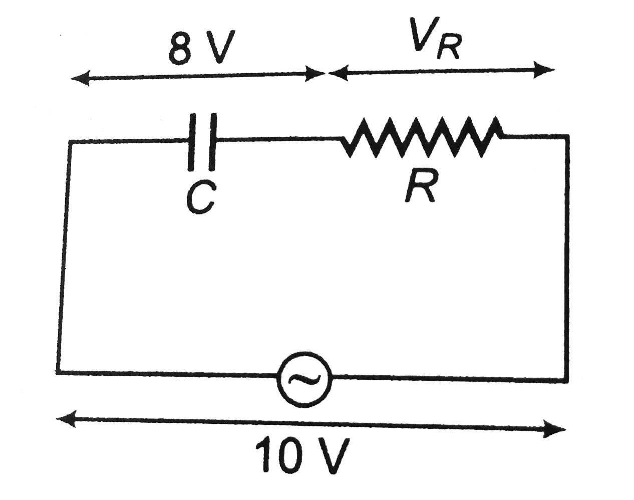
In a series C−R circuit shown in figureure, the applied voltage is 10V and the voltage across capacitor is found to8V. The voltage across R, and the phase difference between current and the applied voltage will respectively be
 .
.
View SolutionIn a series C−R circuit shown in figureure, the applied voltage is 10V and the voltage across capacitor is found to8V. The voltage across R, and the phase difference between current and the applied voltage will respectively be
 .
.
View SolutionIn an AC, series L-C-R circuit, R=XL=XC and applied AC, voltage is V. Then match the following two columns.

View SolutionAnswer the following:
(a) Explain the term 'Sharpness of resonance' in ac circuit.
(b) In a series LCR circuit , VL=VC≠VR. What is the value of power factor for this circuit?
View SolutionIn a series L−C−R circuit, currenrt in the circuit is 11A when the applied voltage is 220V. voltage across the caspcitor is 200V. If the value of resistor is 20Ω, then the voltage across the unknown inductor is
View SolutionIn a series L.R circuit, power of 400 W is dissipated from a source of 250 V, 50 Hz. The power factor of the circuit is 0.8. In order to bring the power factor to unity, a capactor of value C is added in series to the L and R. Taking the value of C as (n3π)μF, then value of n is ____________
View SolutionIn a series L−C circuit, the applied voltage is V0. if omega is very low, then the voltage drop across the inductor VL and capacitor VC are
 .
.
View SolutionIn a series LCR circuit, voltage drop axross L can be more than applied voltage (True/false).
View SolutionStatement 1: In a series RLC circuit if (VR),(VL)and(VC) denote rms voltage across R,L and C respectively and (VS) is the rms voltage across the source. Then (Vs)=(VR)+(VL)+(VC)
Statement 2: In ac circuit, Kirchhoff's voltage law is correct at every instant of same.

View SolutionIn an AC circuit , current is 3A and voltage 210V and power is 63W. The power factor is
View Solution
